Cast-in-place longitudinal joint between precast T-girders

Hello everyone,

I am currently investigating whether and how a longitudinal cast-in-place concrete joint between the top flanges of precast T-girders can be realistically modelled in RFEM.

The global superstructure has already been analysed using a folded-plate model, and the internal forces in the joint have been derived from that model. These design forces are now intended to be transferred into a local RFEM model in order to study different geometric configurations of the joint.

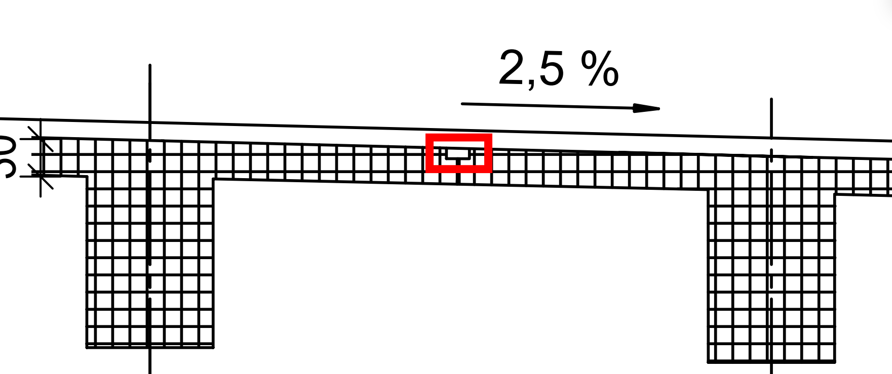
The joint consists of:

  • a cast-in-place concrete infill between the adjacent top flanges,
  • reinforcement projecting from the precast elements into the joint,
  • and it is intended to provide bending moment capacity (moment-resisting connection).

My objective is to investigate different joint geometries and evaluate the resulting stress distribution and structural behaviour.

My main questions are:

  1. Does it make mechanical sense to model the joint as a surface (shell), or should it be represented as a 3D solid (volume element) to realistically capture bending moment transfer?
  2. What would be the recommended modelling strategy in RFEM for such a moment-resisting precast concrete joint?
  3. In initial attempts using surface elements for stress analysis, I did not obtain meaningful results — are there typical modelling pitfalls in this context?

Any guidance or modelling recommendations would be greatly appreciated.


Hi Reiner,

Welcome to the Community! :blush:

Thanks for your question — happy to help!


:one: Modeling Approach

This question is not easy to answer in general terms, as it strongly depends on the required level of detail.

To achieve the most accurate results, modeling with solid elements (volumetric bodies) provides the highest level of detail. This is particularly relevant if you want to realistically represent:

  • The longitudinal joint

  • Possible connection reinforcement

  • The grouting mortar

  • The interaction between the individual components

With this approach, you can also evaluate member internal forces in detail.

However, whether this is the best solution for you depends on factors such as:

  • Required accuracy

  • Computation time

  • Project complexity

I cannot assess from here whether this approach is optimal for your specific case.


:two: Recommendations

At the moment, we do not have any general recommendations for this specific scenario.


:three: Evaluation of Your Results

Without additional information (e.g. model setup, boundary conditions, material properties, results screenshots), I’m unfortunately not able to comment on or interpret your results.

As we do not have much experience ourselves, I cannot name typical problems as well.

If you can provide more details, I’ll gladly take another look. :+1:

Looking forward to your feedback!

Best regards
Stefan Hoffmann