Create a "clamped" glass pane between aluminum profiles

Hi everyone!

I'd like to properly model an aluminum frame, that recieves (a little) stabilization via glass panes that are "clamped" in between the aluminum profiles and a "lid" that you simply push / hammer down.

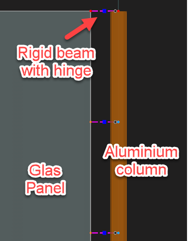
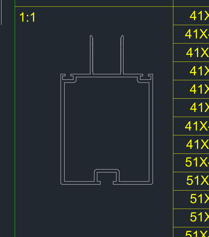
The first image shows the profile that's load bearing.

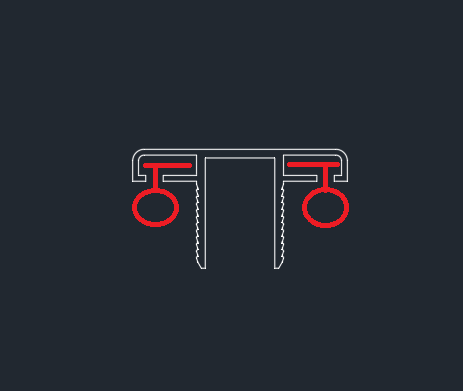
The second image represents the same first profile, but where i've marked in red where the glass would be placed, and thereafter a lid that's pushed down. The lid is not load bearing.

Now, the glass panes shouldn't take take any vertical loads, and neither should they reinforce the profiles.

However, in higher wind loads i get stability issues in my model (20 meters up in high wind zones..) so quite extreme conditions for a medium sized greenhouse.. The deflection also becomes to large for comfort, but i also know from simple experience that when we place the glass in the structure and clamp the lids on, the whole thing acts more as a "package" and instantly becomes more stiff and way less flexible. Compared to how it acts without any panes. I'd like this to be represented, accurately and safely, in the modelling.

Now i don't want the glass in the model to take all horizontal loads, we do have tension members that are the primary load bearing element for this. But is there some smart way to model the glass panes in the model in order to make the structure as a whole more stiff?

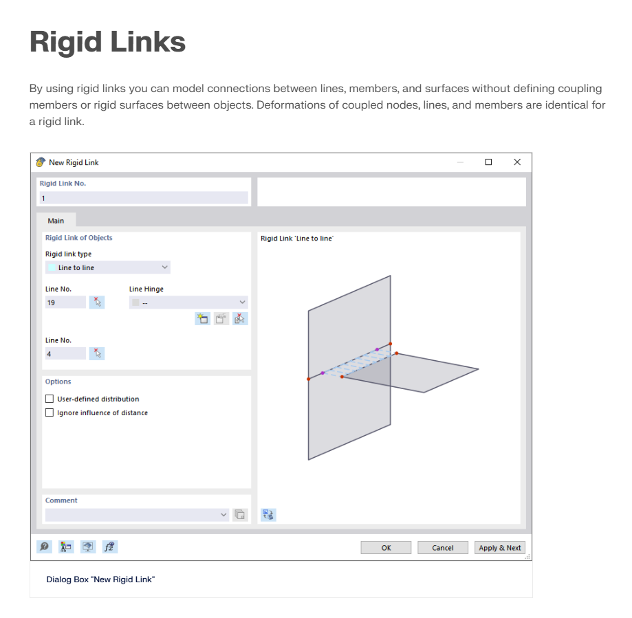
I suspect line hinges are necessary, but i'm sure there's plenty of settings, both in the line hinge interface but also in general while modelling that i quite frankly have no idea on how i should utilize to get a result that's somewhat accurate to real life behaviour of the structure and the glass effect on it.

I'd appreciate any tips, tricks and suggestions on how i can create a good and accurate model. :slight_smile: If you'd like to help, but feel like there's important information missing, feel free to ask me and i'll see what i can get a hold of! I'm not very accustomed to these types of lightweight structures so i apologize in advanced for the poor description.

Best regards,
Tobias M.

Hi Tobias,

You can create glass surfaces between the aluminium columns and connect them at the connection points using rigid beams.

To ensure that the area load acts only on specific members, you can use the Member Loads feature from the Area Load Wizard.

For more detailed instructions, please take a look at our manual here: RFEM 6 Manual.

Let me know if you need any further assistance! :+1:

Best regards
Matthias

Hi Matthias,

Thank you for the answer!

I'm a big fan of the wind & snow load wizards.

I'm currently utilizing load surfaces between the aluminum profiles, which i'm applying the load to. I filter out the profiles via Object selection filters.

So currently the load panels are the only ones primarily getting the load, which then spreads that onto the members. not sure if i even need to remove the members like this or if the program understands that it shouldn't apply the loads twice..

Anyhow, the rigid beams you're reffering too, are these the so called rigid links i managed to find in the manual you so kindly sent my way? Or are they actually called "rigid beams" ? If so i might give it a go and dig myself a bit deeper into how it works and what settings i should use more specifically.

If i may ask, in what way would these rigid links improve the modelling, as opposed to simply modelling the glass panes with a shared lined to my aluminum profiles?

Would it make the model more flexible in the sense that i could perhaps change the settings of the surface, without affecting the line that my profiles are based from?

(because that's one thing i've noticed when designing the panes with a shared line with the aluminum profiles, that when i apply line hinges to open up for rotation of the planes, things get unstable quickly in the entire model)

Another part of me is curious if there's some logic in creating the profiles as surfaces instead of members. and thereafter applying surface contact types for friction between the glazing and aluminum profiles. I noticed you had a seminar that did a similar thing for a aluminum - glass railing. But it doesn't feel quite right.. Still a bit lost here on the proper way forward i must admit.

Wish you the best and once again, thank you for your answer!

Hi Tobias, :waving_hand:

A rigid beam is a simple member of the type rigid. You can check out more details in the manual here.

If you use rigid beams as I suggested, you'll be able to model the punctual connection of the glass panel to the beam. On the other hand, a rigid link would create a continuous connection along the entire length of the column. If the panel is clamped along the full height of the columns, then rigid links would be the better option for your case.

For your purpose, I don't see any particular benefits in modeling the aluminum columns as surfaces.

To analyse your stability problem more precisely, the model file would be very helpful:

:right_arrow: Click on FileSave as and choose the following settings to reduce the file size:

image

image467×393 7.53 KB

:right_arrow: Then upload the file here (e.g. *.rf6, *.rs9) – this way, the community can also contribute to the solution.

:owl: Prefer not to share the file publicly? No problem – send it to me via direct message: click on my profile picture or user nameMessage.

Let me know if you have any more questions! :blush:

Best regards,
Matthias

1 Like

Hello again, and once more, thank you for the answer!

I see, now i understand your thought process.

For clarification, the glass panes are clamped along their entire length. So a punctual / nodal connection in the form of rigid beams that you suggested, would in this case be "wrong" or less correct. But non the less, great tip that i'll carry with me for future projects when i do need more localised connections. So thank you!

Moving back to the issue at hand, i'll see if i can make some magic with rigid links. But i might send you the model regardless once i feel like i'm "stuck". Perhaps you can point out a few things that could improve the model as well as some better modelling practices. Being a rookie I can image there's a few pointers here and there that could use some love and adjustment from a more experienced user haha. I'm using quite a lot of "pinned" member hinges in the model, which i believe could be a reason why the model easily becomes unstable.

The tension members also don't cross properly, so i'm almost certain i'll need the panes to act like diaphragm sheeting, although a very small effect.. but to some degree at the very least.

As you can see in the images, there are "tooths" that lock the profiles together.
In the lid, you place a EPDM rubber sealing strip (illustrated in red), and then you squeeze the lid and profiles together with the glass resting in between.

So the glass can't move sideways, but there's some slippage at the very top of the window panes, but there should be quite a lot of friction preventing movement due to the EPDM strip. The reason we leave a bit of space at the top is so that the glass don't get "crushed" or carry any weight once the eaves beams bend due to loading.
So in practise, the windowpanes can slide up and down (if it can overcome the friction of the rubber strip), but are prevented from sideways motion. There might be some tolerances of a few mm at most, but the whole thing should, all in all, be fairly restrained.

Well, i'm all over the place clearly, and a bit over my head as well.. This isn't really any type of work i'm used to, so i really do appreciate your guidance on the matter.

I'll keep in touch once i reach a certain level of satisfaction in my model, and then i'll send it your way :grinning_face_with_smiling_eyes:

1 Like