Hello everyone,
I have a question regarding the Steel Design add-on and the calculation of Mcr.
I am working with a 2D rigid frame and using the default Eigenvalue Method for the evaluation of Mcr. What I am trying to understand is how the amplifier αcr is actually determined.
The value of αcr used for Mcr does not match any of the critical load factors from my regular stability analysis of the full frame.
To investigate this further, I also created a separate model containing only the specific member and tried to reproduce the same moment distribution, but I still could not obtain the same αcr value.
I understand that the value is related to the relevant LTB mode, but I would like to understand more precisely:
- How is αcr determined internally in the Steel Design add-on?
- Is it based on a separate member-level eigenvalue analysis rather than the global frame stability analysis?
- Which assumptions are included, for example regarding effective boundary conditions, moment distribution, load application, or warping/torsional restraints?
Any clarification would be greatly appreciated.
Kind regards,
Jannick
Hi JannickHansen,
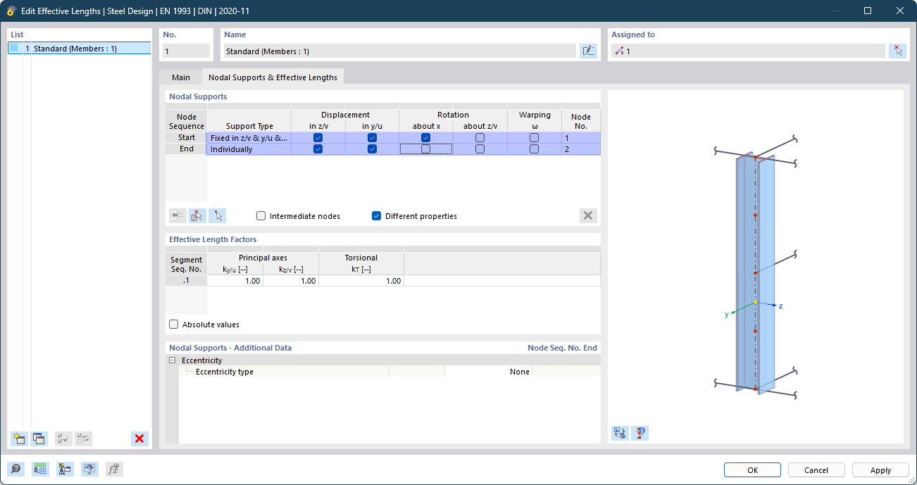
Thank you for your question!  Let me provide some clarification regarding the calculation of the αcr factor in the Steel Design Add-On. The αcr factor is determined using an eigenvalue solver, where the design object is extracted from the system for the eigenvalue analysis. The boundary conditions are defined by the nodal supports of the effective lengths (see image below).
When comparing the critical load factors between the Structure Stability Add-On and the Steel Design Add-On, there are a few important points to consider:
-
Analysis Scope:
The Structure Stability Add-On always performs the eigenvalue analysis on the entire system. In contrast, the Steel Design Add-On conducts the analysis on the isolated member or member set.
-
Forces Considered:
The Structure Stability Add-On only considers axial forces in the members. If the Add-On “Torsional Warping” is activated, all internal forces are considered in the eigenvalue solver. On the other hand, the Steel Design Add-On considers both axial force and bending moment My in the eigenvalue solver, which are the relevant internal forces for lateral-torsional buckling.
-
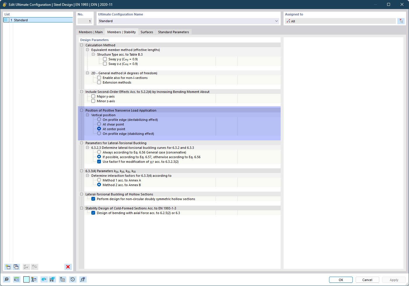
Load Application:
For a meaningful comparison, ensure that the load application points match. For instance, if you applied the loads at the center of gravity in the main system, make sure that the correct settings are chosen in the Steel Design Add-On in the Ultimate Configuration. Please refer to the image below for the correct setup.
-
Amplifier αcr vs. Critical Load Factor f:
It’s important to note that αcr is not directly comparable to the Critical Load Factor f from the Structure Stability Add-On. The Critical Load Factor f indicates how much the applied loads must be increased for the system to become unstable. The αcr factor, however, is specific to bending moment My and indicates the factor by which My needs to be increased for instability to occur, while all other loads remain the same.
I hope this clarifies your question!  Feel free to reach out if you need further assistance.
Best regards
Niklas Wanke
If none of the settings provide you with the value for M_cr that you expected, it could also be because you forgot to apply the load eccentrically in your stability analysis model.
The same thing happened to me once by accident. While in steel design, the bearing capacity configurations of the add-on clearly define where the load acts for the verification regardless of whether the member load has defined an eccentricity, for a correct eigenvalue calculation, the member load must be entered eccentrically so that it acts on the top flange!
Best regards,
Nick