Hi! I am writing a research paper about lateral-torsional buckling with timber structures and I had a question about a topic discussed on your website: Lateral-Torsional Buckling in Timber Construction | Theory.
In this article, the formula for the Effective Length Considering Elastic Rotational Spring, Restraint, or Member Elastic Foundation is given, this formula is from the German national annex so I'm unfamiliar with it.
In the factors alpha and beta are the springs/foundations Ky, KG and Ktheta. I am wondering how these are determined.
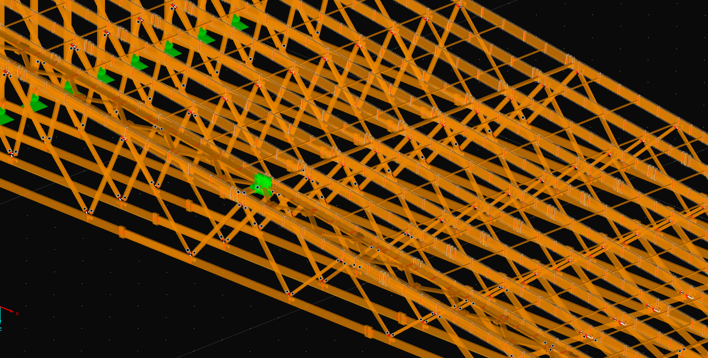
Since Ky is measured in N/mm2 it seems like it's an elastic foundation over the entire length of the beam (N/mm / mm). In my case I am looking at prefabricated roof elements, so Ky would be the battens, fastened at the top of the beam. I would expect a different behaviour from multiple lateral springs with a stiffness in N/mm compared to an elastic foundation over the entire length of the beam.
Moreover, calculating the stiffness of the batten (or rather its staple connection which seems to be authorative) is another question in itself.
I hope you could share some insight in how these springs/foundations should be approached within the framework of roof elements.
Thank you in advance.
Hi JElling,
thank you for your question.
There is another article listed by the one you mentioned.
https://www.dlubal.com/en/support-and-learning/support/knowledge-base/001669
In this one is the determination of the springs/foundation explained.
Another helpful article can be found in the net here.
https://informationsdienst-holz.de/publikationen/4-holzbau-statik-aktuell/stahltrapezelemente-zur-aussteifung-hoelzerner-dachkonstruktionen
I appologize it is only in german but the equations in the PDF that you can download there are hopefully self explaining.
If you like to regard battens the most simple way is to calculate an Equivalent force. I attached a small Excel Sheet and further literature for it.
A more detailed modelling of course would also be possible, where the battens are directly modelled in a 3D model.
I hope this answers your questions. Let me know if you have any others and I`ll be happy to help.
Best regards
Bastian Kuhn
Summary.pdf (256.0 KB)
Ersatzlast.zip
Hi Bastian,
Thank you for your reply!
I have one more question. A bit theoretical perhaps, but something about the formula for Lef (regarding the stiffness of the foundations) is unclear to me, specifically the way the factor beta is calculated. 1 / (a * b) serves as a scalar to the rest of the formula. If we assume that the Kg = infinite, then Alpha = 1,0. Then the only influence becomes Beta.
If I take a very low, but constant value for Ky, and only increase the length of the beam. The Beta factor skyrockets, therefor decreasing the total effective length, this seems counterintuitive. If I keep increasing the length of the beam, the effective length can go negative.
Is there something I am missing, or is this a flaw in the formula?
Thank you in advance.
Hi, do you have numbers, then we can compare your results with mine. I do not see an issue here. Low stiffness results in beta factor of 1 (effective length will be increased) and high stiffness brings beta to infinity (leads to 0 length). Did you read the last paragraph of this article?
There is a better analytical approach described here:
Hi Gerhard,
Sorry, I misused the term 'negative' effective length. I didnt mean an Lef smaller than 0, but an Lef smaller than the centre-to-centre distance of the laterial supports.
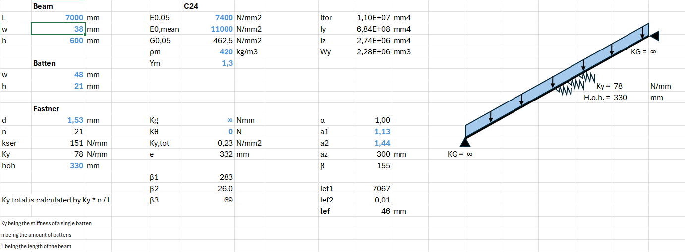
In my case, I have a beam that gets supported with battens every 330 mm. The connections of these battens are not very stiff so I dont expect them to have a big influence on the effective length, therefor it seems weird that the Lef can become smaller than 330 mm.
Secondly, the Lef still becomes smaller only when increasing the length of the beam.
Below 2 examples.
In the spreadsheet, formulas for Beta (b1, b2 and b3) and Lef are split into chunks for readability. They are properly calculated.
I have read that the formula becomes invalid at some point, but seeing how the lateral supports are not very rigid, I doubt this issue has to do with the beam having several mode shapes.
I hope this clears any confusion.
It is exactly the same issue as described in my article.
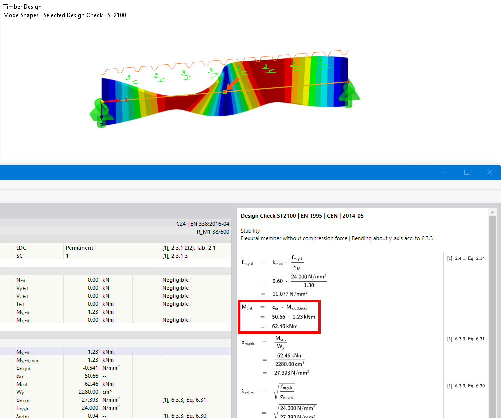
The eigenshape shows it clearly:
The eigenvalue solver gives you a M_crit of 62,5 kNm.
This leads to an effective length of 0,5m, which is plausible.
This is sufficient proof to show that this equation leads to incorrect results.
Please use the approach from my second article in case you want to check analytical solutions.
1 Like