Good morning,
I am having trouble or I am not sure if it is possible to make the following connection with the steel joints add-on for RFEM 6.
I have the following design:
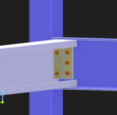
It is a continuous square tubular section post, in which I want to join two beams. One of them is a beam with a C-shaped cross-section (white) that inserts into the U-section beam (blue). I want to know if it is possible for the L-shaped sleeve to be bolted on one side to the web of the U beam and on the other side to be bolted both to the web of the C beam and to the web of the square tubular beam.
Currently, I get an error because the sleeve plate intersects with the web of the C beam (white).
Any information on whether this connection can be made or not will be very helpful.
Thank you very much.
Best regards
Hi FelipeDosset,
thanks for your message!
To analyse the problem more precisely, the model file would be very helpful:
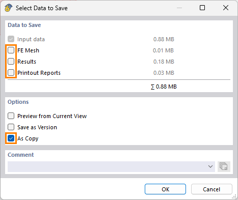
 Click on File → Save as and choose the following settings to reduce the file size:
Then upload the file here (e.g. *.rf6, *.rs9) – this way, the community can also contribute to the solution.
 Prefer not to share the file publicly? No problem – send it to me via direct message: click on my profile picture or user name → Message.
Best regards
Gerhard Rehm
Hi Good Morning,
Ok, i uppload here, i hope you can analize clairly.
TFM_FelipeDosset_STEELJOINTS.rf6 (1,5 MB)
I am tryinng to define the joint in the node nº 18.
Thank you very much.
Best reggards.
Thank you for the file.
-
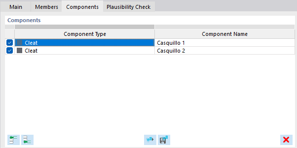
A member cut is not needed, because the component "Cleat" has it included directly. This is enough:
-
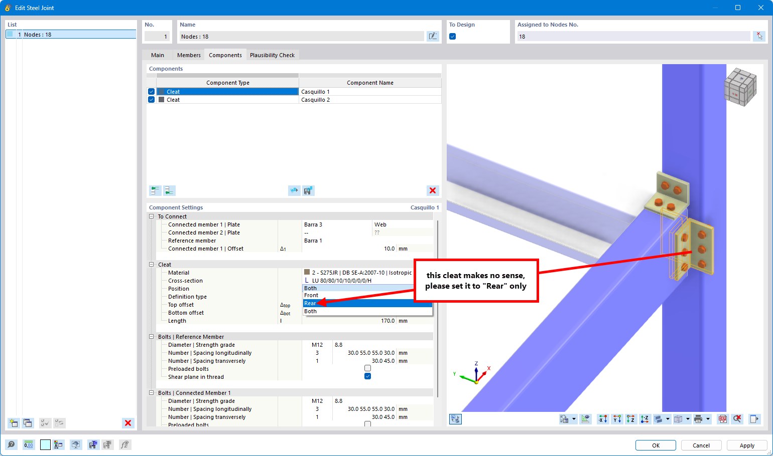
The front cleat makes no sense
-
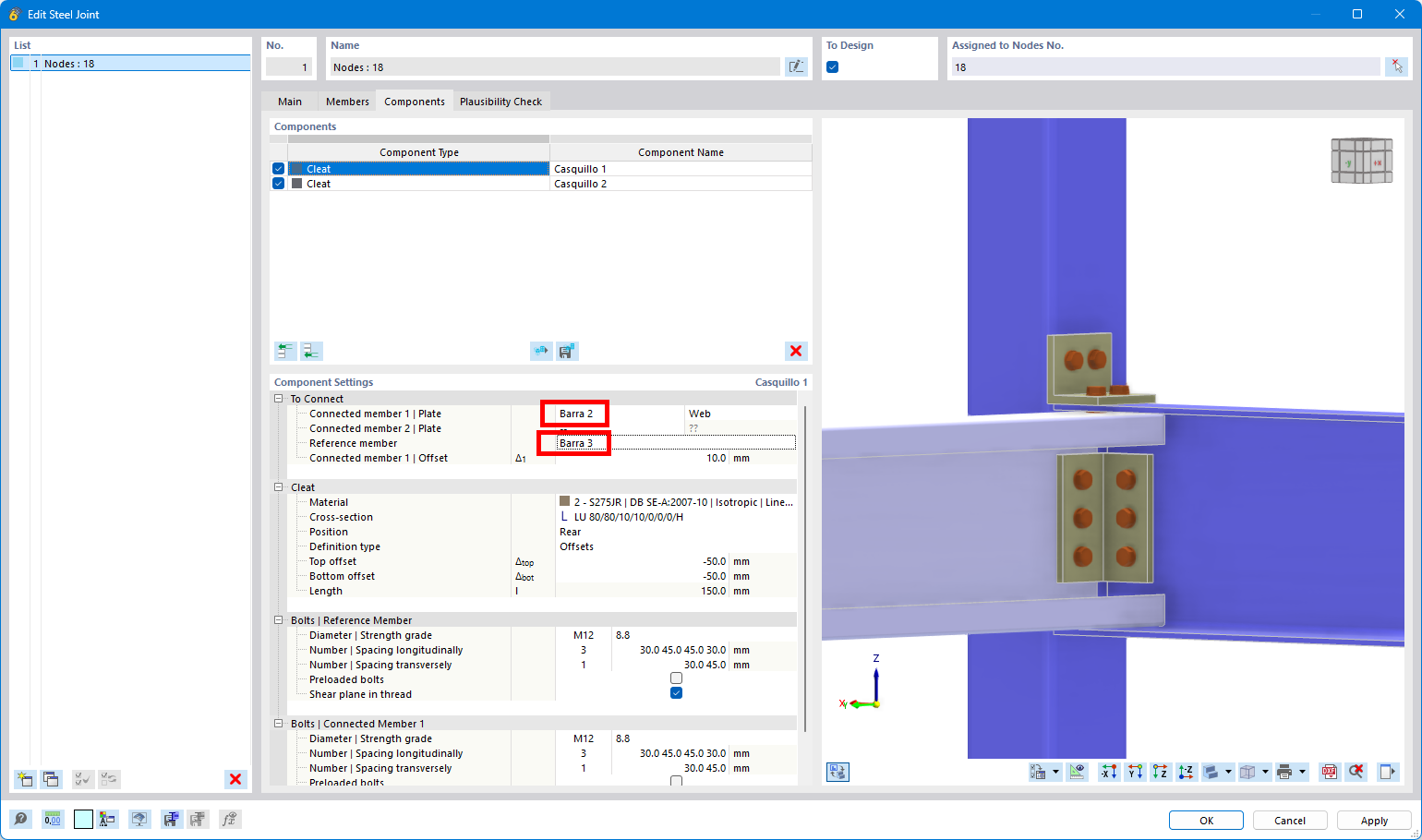
Connect member 2 with member 3. When you connect member 3 with member 1 the web of the C-section is not considered:
-
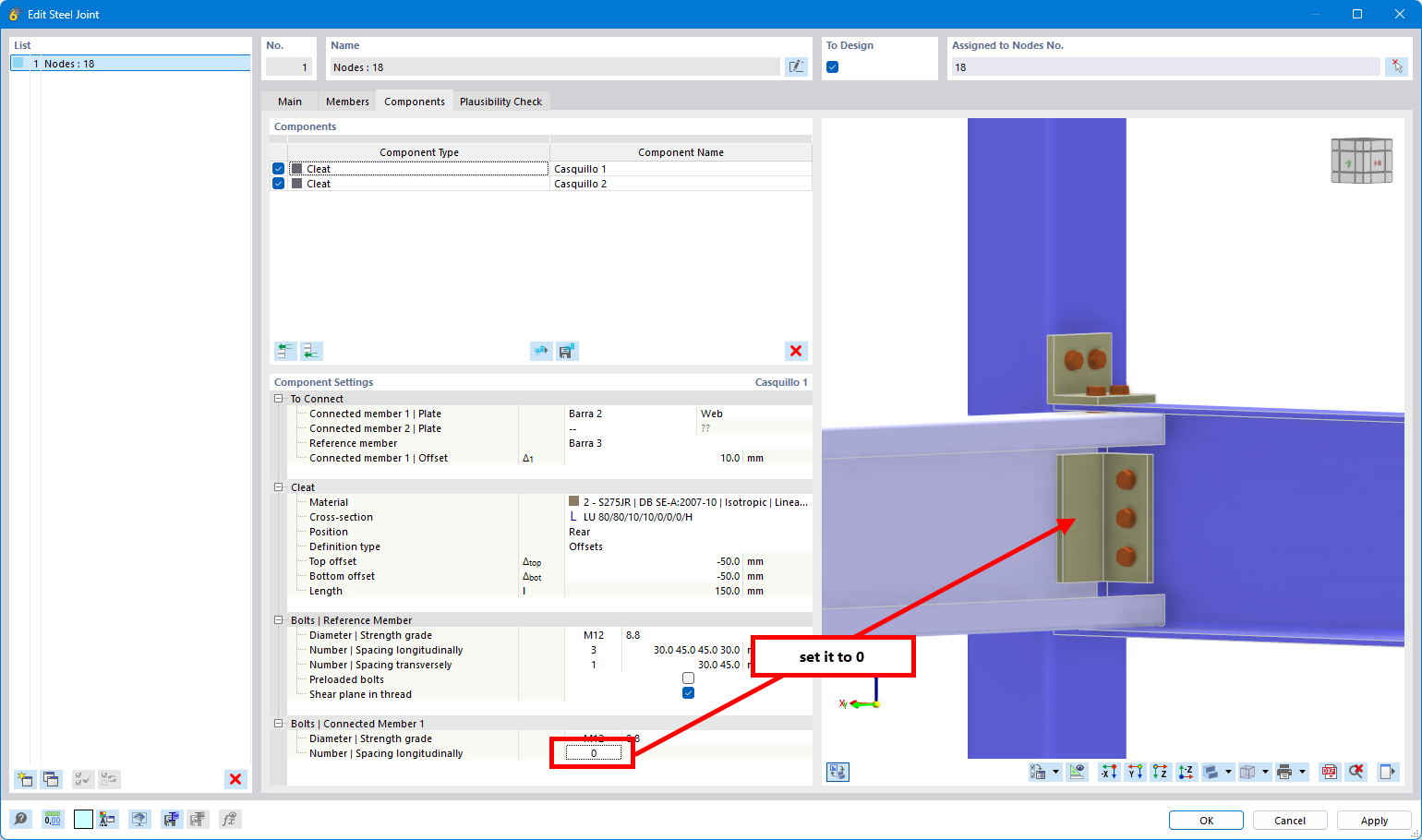
Now there is the problem, that you cannot directly connect all 3 plates with the bolts with plate components. Please use this workaround:
-
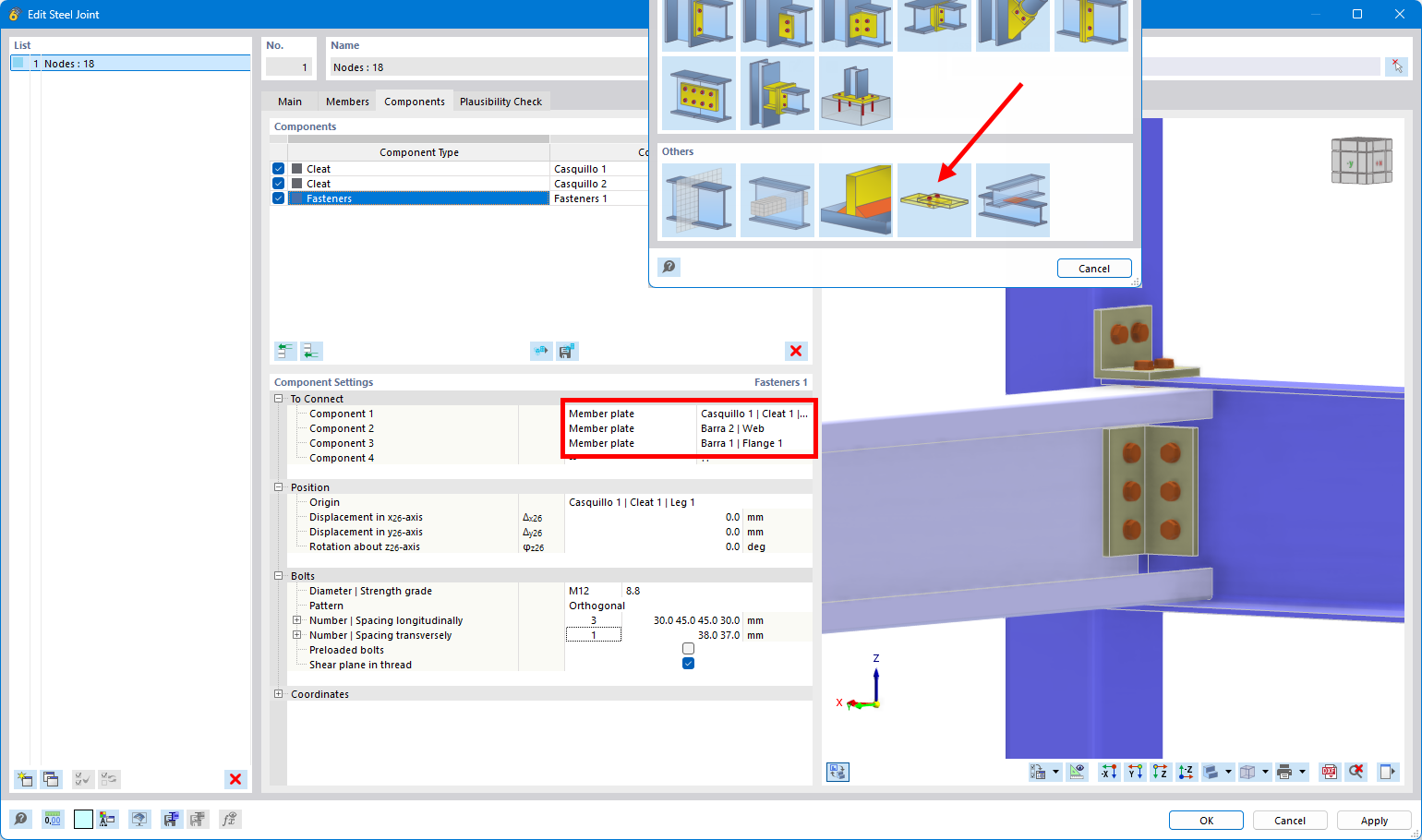
Insert bolts manually and defined that the bolts should go through all 3 elements:
-
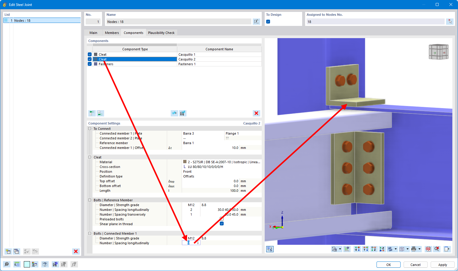
Repeat the same for cleat 2:
-
Inser bolts manually:
-
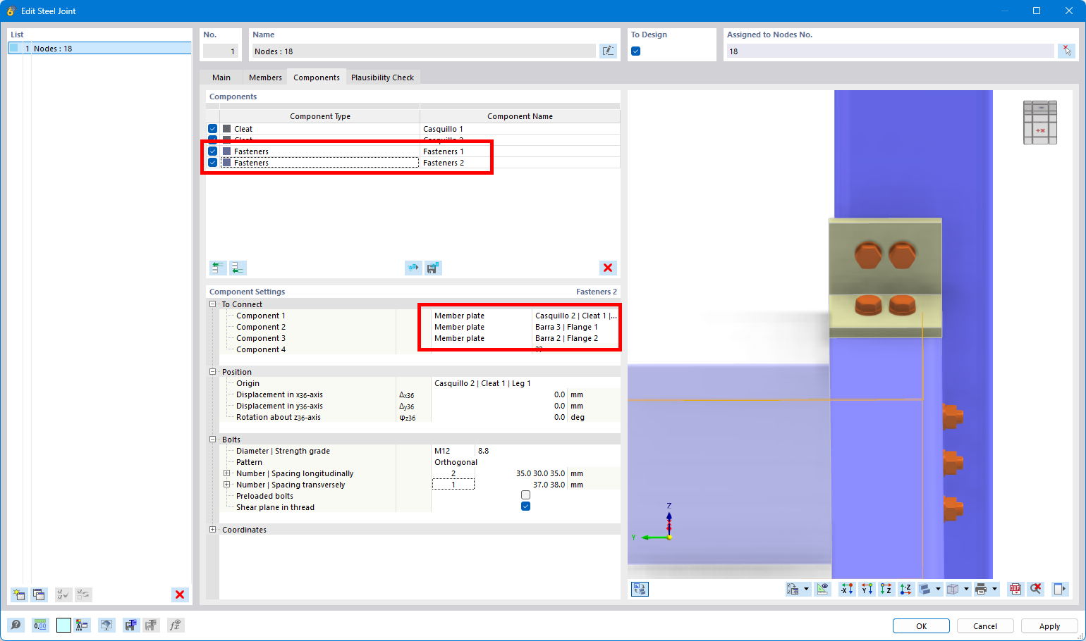
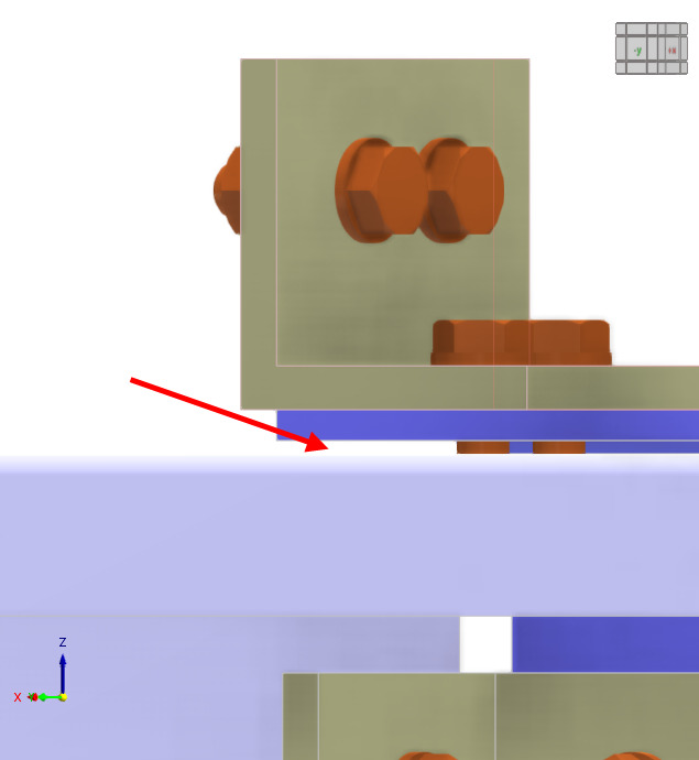
As you can see, there is a gap between the flanges:
Since it is small, it has not such an high influence and calculation is possible. In case you wanna have a proper connection, you need to define member eccentricities to allign the components perfectly. I have attached the file (without member eccentricities).
TFM_FelipeDosset_STEELJOINTS.rf6 (1,5 MB)
Thank you very much for the explanation!!
Very kind!
Best regards