Understanding problem result cut evaluation/comparison result bar

Good day again,

I am currently having some difficulties understanding exactly how certain internal forces or resultants of the result sections come about:

send_without_results_Dlubal.rf6 (2.3 MB)

If I look at the results in load case 1008 of result section 5 in my file “send_without_results.rf6”, which is assigned to surface 73, a resultant load in the global X-direction of 11.15 kN can be observed here.

image

This is very surprising to me because the global x-axis in this case is identical to the local y-axis of surface 73.

Surface 73 is an orthotropic surface with a modulus of elasticity as follows:

image

Accordingly, internal forces of ny = 0 kN/m occur over the entire surface, so how can it be that a resultant force of 11.15 kN of the result section is still output in the direction of ny?

image

When I tried to trace the weld seam stresses for a connection generated from the steel connection addon, I encountered similar questions:

For connection 1 of the file “Anschluss_Addon_global”, a fillet weld verification of weld seam 2 results in 0.219 based on the design according to load case 1 as follows:

Anschluss_Addon_global_noResults.rf6 (1.7 MB)

image

If I then look at the resultant forces of the result section in the submodel, they are composed as follows:

image

According to my logic, a force FW|| of 0.02 kN would act. With a weld length of 340 mm and a thickness of a = 3 mm, I would calculate the following stress: tau = 20 N / (340*3/cos(45)) = 0.01386 N/mm². How can it be that the addon arrives at tau|| of 25.5 N/mm²? Is it perhaps not the case that the resultants of the result sections are used for the analytical verification of the directional method in the design details? If this is not the case, it would be great to know exactly how the internal forces or stresses are determined that are used for the analytical weld seam verifications of the addon.

I would be very pleased to receive feedback.

Best regards,

Nick Böttcher

Hello @DeflectionPerfection :waving_hand:

The force in the local y-direction of the surface results from the shear displacement. Since the shear modulus G,xy is not equal to 0, shear stresses can be absorbed in this direction.

Please take a look at the internal force n,xy in the weld seam.

The weld seam verification in the add-on Steel Connections is not carried out with the resulting internal forces, but stress-based. This is exactly what is enabled by representing the seam via the surface model.

This means:
For the comparison with the limit stresses according to the directional method, the stresses at every point of the result section are used.

Best regards
Fabian

Many thanks!

I had completely omitted the sliding here by mistake, so I have now become significantly wiser :smiley:. However, I am unfortunately facing the next challenge in the weld seam evaluation. In the attached file:

Anschluss_Addon_global_noResults.rf6 (1.7 MB)

1 exemplary connection was recalculated using the addon for Lk1 and then the design details were examined.

This results in the following design details for weld seam 1:

image

In the associated submodel, weld seam 1 corresponds to area 69.

The result section of area 69 gives maximum values for the base stress tauxy of +12.425 N/mm² and -12.721 N/mm². Since sigma y according to the modulus of elasticity Ey = 0 => = 0, I assumed that tauparallel should be equal to tauxy, but unfortunately I seem to be making a mistake here again or the stresses in the design addon are not taken directly from the stresses of the result section without further correction factors.

image

I would be very grateful for further help.

Best regards,

Nick Böttcher

Hello @DeflectionPerfection,

The material model of the weld seam is very complex because it has to represent the two different failure criteria (equivalent stress and normal stress).

It is not a classic von Mises material model (p,x != 1), but the relevant stresses are the von Mises equivalent stress and the normal stress perpendicular to the seam.

Therefore, one stress component (here tau,II) must be expressed as a function of the others. The equivalent stress, the normal stress, and the shear stress perpendicular to the seam are exactly those from the result sections in the substitute model.

Best regards
Fabian

I would also assume that! Therefore, I integrated the following code into my program:

def perform_weld_seam_stress_verification(RFEM_app, lc_no, Node1, Node2):

"""searches for weld seam stresses in FE nodes per load case per weld seam and outputs the design value tau_parallel"""

filters_Welds = [

    rfem.results.ResultsFilter(

        column_id="FE_NODE_NO",

        filter_expression= FENODES

    )

]

Weldresults = rfem_app.get_results(

        results_type=rfem.results.ResultsType.STATIC_ANALYSIS_SURFACES_BASIC_STRESSES_MESH_NODES,

        filters=filters_Welds

        ).data


df_node1 = Weldresults[

    (Weldresults["mesh_node_no"] == Node1) &

    (Weldresults["loading"] == lc_no)

]


df_node2 = Weldresults[

    (Weldresults["mesh_node_no"] == Node2) &

    (Weldresults["loading"] == lc_no)

]


# 👉 Extract values per tag

Mesh_Node_1_tau_xy = df_node1[df_node1["tag"] == "top"]["tau_xy"].iloc[0]

Mesh_Node_1_tau_xz = df_node1[df_node1["tag"] == "middle"]["tau_xz"].iloc[0]

Mesh_Node_1_sigma_x = df_node1[df_node1["tag"] == "top"]["sigma_x"].iloc[0]


Mesh_Node_2_tau_xy = df_node2[df_node2["tag"] == "top"]["tau_xy"].iloc[0]

Mesh_Node_2_tau_xz = df_node2[df_node2["tag"] == "middle"]["tau_xz"].iloc[0]

Mesh_Node_2_sigma_x = df_node2[df_node2["tag"] == "top"]["sigma_x"].iloc[0]


tau_xy_Stresspoint_1 = calculate_average(Mesh_Node_1_tau_xy, Mesh_Node_2_tau_xy)

tau_xz_Stresspoint_1 = calculate_average(Mesh_Node_1_tau_xz, Mesh_Node_2_tau_xz)

sigma_x_Stresspoint_1 = calculate_average(Mesh_Node_1_sigma_x, Mesh_Node_2_sigma_x)


# Calculation of flank stresses  

Flank_normal_stress = sigma_x_Stresspoint_1*0.70710678 + tau_xz_Stresspoint_1*0.70710678

Flank_comparative_stress = (2*(sigma_x_Stresspoint_1 ** 2 - sigma_x_Stresspoint_1 * tau_xz_Stresspoint_1 + tau_xz_Stresspoint_1 ** 2) + 3 * tau_xy_Stresspoint_1 ** 2) ** 0.5


# Utilization ratios

eta_Weld_sigma = Flank_normal_stress / sigmaw_sigma_Rd

eta_Weld_v = Flank_comparative_stress / sigmawvRd


return tau_xy_Stresspoint_1, tau_xz_Stresspoint_1, sigma_x_Stresspoint_1, Flank_normal_stress, Flank_comparative_stress, eta_Weld_sigma, eta_Weld_v               

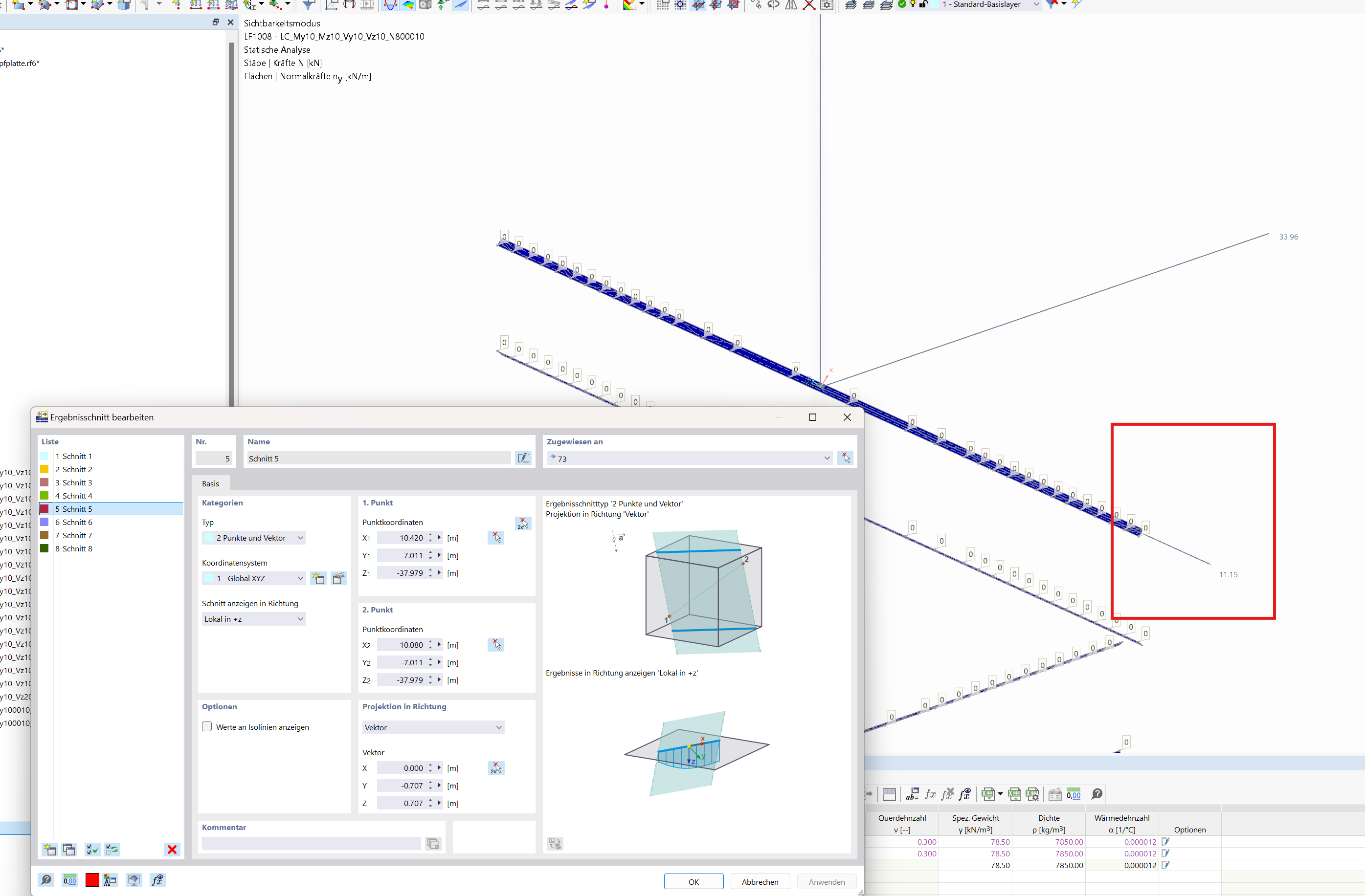
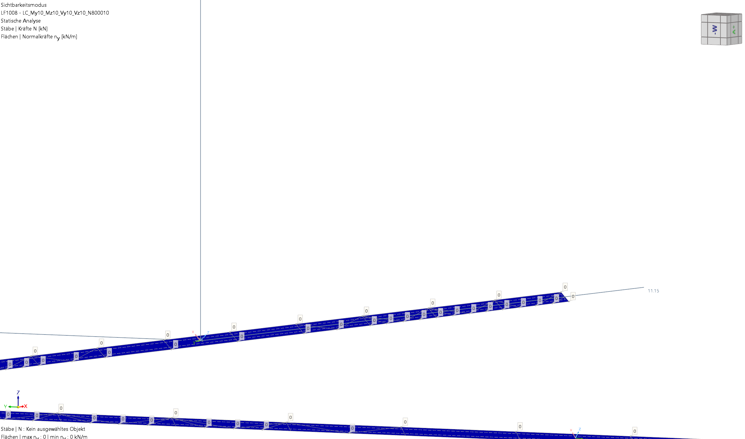
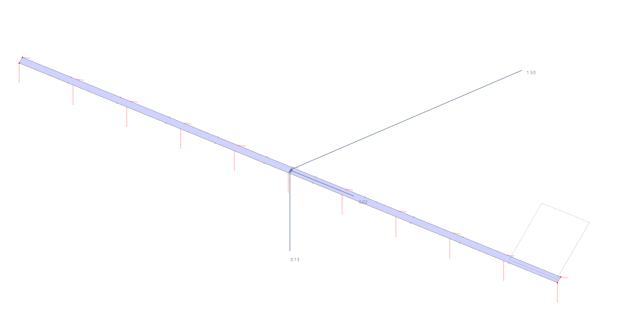
=> My FE mesh in the weld seams is always structured so that there are 2 FE nodes, i.e., Node1 and Node2, across the width of the surface, which together form 1 stress point that consequently outputs the same value as a result section would.

I fear that we might be talking past each other because it is completely clear to me that the relevant stresses cannot be directly read from the basic stresses, hence the following line of my code that determines the relevant stresses:

Calculation of flank stresses

Flank_normal_stress = sigma_x_Stresspoint_1*0.70710678 + tau_xz_Stresspoint_1*0.70710678

Flank_comparative_stress = (2*(sigma_x_Stresspoint_1 ** 2 - sigma_x_Stresspoint_1 * tau_xz_Stresspoint_1 + tau_xz_Stresspoint_1 ** 2) + 3 * tau_xy_Stresspoint_1 ** 2) ** 0.5

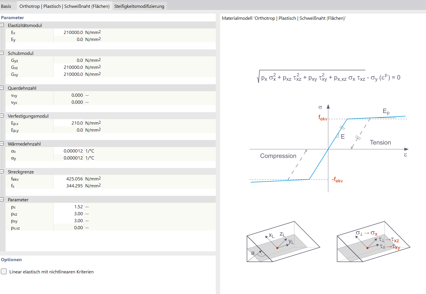
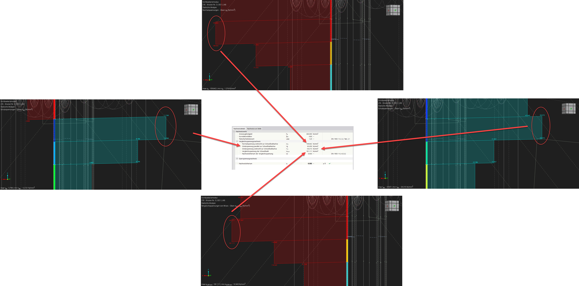
What concerns me here is the stress tau_parallel entering the calculation. According to both my logic and the diagram attached showing the stress components of the weld seam material:

![image|700x264](upload://yQESNgnvva8fi6j7w7C0VNcigi6.png)

tau_parallel would be set here as tau_xy.

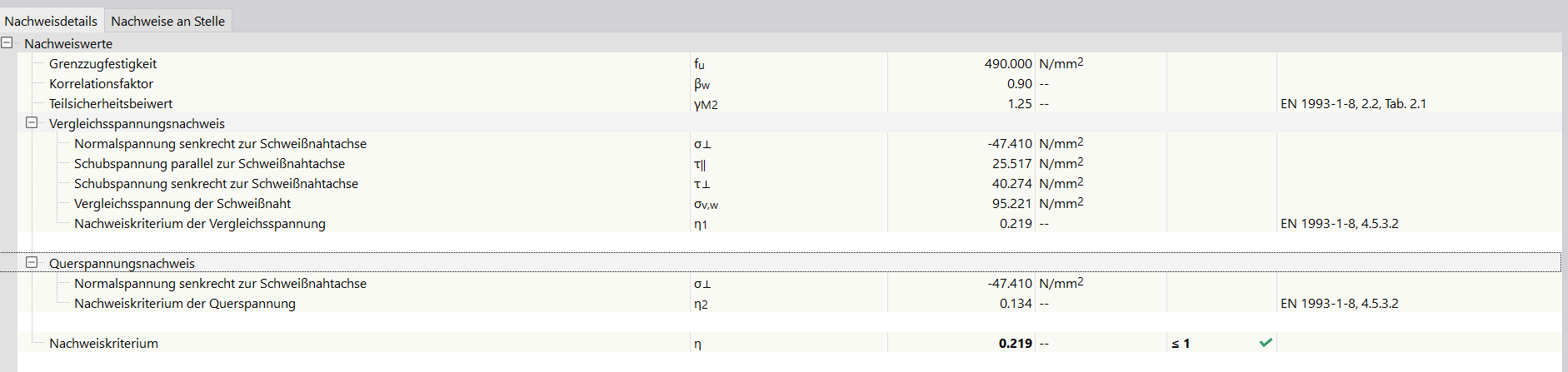
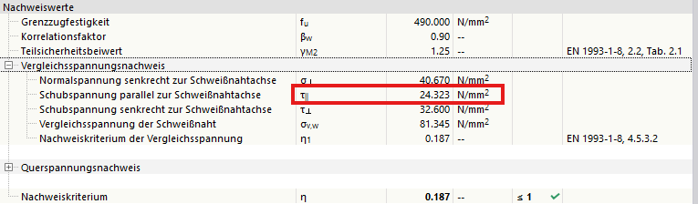
=> Unfortunately, in the design details of the addon, I do not get the matching tau_parallel values corresponding to the tau_xy values from the result sections of the associated submodels (see files above).

If it should be the case that I am not allowed to use tau_xy directly as the variable tau_xy_Stresspoint_1 for calculating the relevant flank comparative stress:

Flank_comparative_stress = (2*(sigma_x_Stresspoint_1 ** 2 - sigma_x_Stresspoint_1 * tau_xz_Stresspoint_1 + tau_xz_Stresspoint_1 ** 2) + 3 * tau_xy_Stresspoint_1 ** 2) ** 0.5

Then it would be great if you could clarify how tau_parallel is not derived solely from tau_xy but depends on the other stress components, preferably with references to literature / FAQ / knowledge base articles or similar.

Edit: I am aware that the differently set tag search by layer side seems somewhat arbitrary, but ultimately it is irrelevant for the weld seams since their stresses are constant through the thickness at each FE node... please just ignore that.

The stress components σ⊥, τ⊥ and the Von Mises equivalent stress can be directly extracted from the result section through the weld seam under constant net results.

Due to the adapted material model, the Mises equivalent stress is not consistent with the basic stress components, which is why τ∥ is determined from it.

image

Unfortunately, there is no documentation on this. However, here is another image that hopefully clarifies the procedure.

image

Best regards
Fabian

2 Likes

Wow, thank you so much!

It's really great that all this knowledge is shared and conveyed by you!

I appreciate the extent to which you have accompanied me in my task here and am extremely grateful for it.

I was quite aware that it was probably almost cheeky to dig so deeply and extensively here and to ask further questions/problems, but Dlubal has once again proven that your support operates at the highest level and offers maximum transparency!

My interface/program is now almost finished, and this would not have been possible in this time without this support.

Many thanks and best regards,

Nick

5 Likes