Freezing a Form-Finding Surface: How to Obtain a True Surface (Not an FE Mesh) in RFEM 6 or via CAD?

Hello everyone,

I am currently working with RFEM 6 and the Form-Finding module to design a membrane tensile structure. The form-finding analysis itself works perfectly, but I am encountering a problem in the next stage of the workflow.

My final goal is to obtain the deformed equilibrium shape of the membrane as a true continuous geometric surface , i.e., a surface that is frozen in its final shape and no longer dependent on the finite element mesh. Ideally, I would like to have this surface directly inside RFEM 6 (for example, to use it as the starting geometry for a new model), although exporting it to a CAD program would also be perfectly acceptable.

As far as I know, the common workaround is to export the final geometry to a CAD program (such as AutoCAD), reconstruct it as a clean surface there, and then import it back into RFEM as a new reference geometry. Unfortunately, I have not been able to make this workflow work either, because every export option I have tried produces only curves or finite element meshes rather than a true surface.

These are the export methods I have tested so far using the standard version of AutoCAD:

  • 3D Scene Export to DXF (right-click): Exports only the boundary lines and nodes (wireframe), with no surface information.
  • AutoCAD Export (File menu): The export fails silently; no file is opened or generated.
  • DXF II Export: This option either does not work or does not produce the expected result.
  • Standard DXF Export: Correctly exports the deformed geometry, but represents it as a finite element mesh composed of 3DFACE entities. When I import this file back into RFEM, I obtain a tessellated mesh instead of a single smooth surface.
  • IFC Export: This appears to be a possible solution, but it requires AutoCAD Architecture to import and convert the geometry into a solid or surface. I only have the standard version of AutoCAD.

My questions are therefore the following:

  • Is there an official command, script, or recommended workflow in RFEM 6 to freeze the final form-found shape and convert it into a single mathematical surface within the software itself, independent of the FE mesh?

  • If not, what is the recommended workflow for exporting a form-found membrane as a true CAD surface (rather than a collection of mesh facets), so that it can later be re-imported into RFEM as clean geometry?

Thank you very much in advance for your time and any suggestions you may have.

Hello Alan,

Please be aware that this approach will cause you to lose the self-stress state . However, I do not know the exact objective of your workflow, so it is difficult to assess the best alternative.

In RFEM 6 , you can use initial states to perform multiple form-finding analyses within a single model.

Unfortunately, I cannot provide a direct solution for the workflow you described:

  • An IFC export would only transfer the original geometry.
  • AutoCAD would not be able to reproduce the exact form-found geometry automatically.

Perhaps you could provide some additional details about your intended workflow and the result you would like to achieve. This may help us identify a suitable alternative. :slightly_smiling_face:

Hello Gerhard,

Thank you for the reply.

Actually, losing the self-stress state is exactly what I am trying to achieve. I should also mention that this is for my university thesis project, which is why I am pushing the software a bit outside standard conventional workflows.

To give you more context: I am not designing a lightweight tensile fabric structure. My goal is to design a solid pure compression shell roof for a stadium made of FRC (Fiber Reinforced Concrete). I am currently using the Form-Finding module (and the "Membrane" stiffness type) strictly as a geometric exploit, like a digital version of Gaudí’s hanging models, to find the optimal funicular shape under self-weight. As you can see in my setup, I have already assigned the concrete material and a 50 mm thickness to the surfaces.

STADIO DUE exploit a trazione per FF - lato corto più basso ristretto - versione avanzata (completa).rf6 (6.7 MB)

Now that I have found this equilibrium shape, my intended workflow is:

  1. Extract and "freeze" this exact deformed geometry (both the surfaces and the boundary beams).
  2. Completely discard the membrane pre-tensions (the self-stress state).
  3. Invert/Flip the geometry upside down (along the Z-axis) so it becomes a vault/dome.
  4. Change the surface stiffness type from "Membrane" back to "Standard".
  5. Run a standard static analysis (e.g., self-weight, snow) on this new rigid, inverted geometry to verify that it works in true pure compression.

Given this workflow, how can I achieve this "freezing and flipping" of the form-found geometry?

If this must be done via export/import to convert the FE mesh into a workable continuous surface (NURBS) and re-import it cleanly into RFEM 6, which format and external software would Dlubal recommend? AutoCAD has unfortunately failed to convert the mesh into a usable surface.

Thank you again for your time and guidance!

Thank you for the detailed description.

One option is to export the FE mesh and then try to generate surfaces from it using a CAD program. The most promising approach would probably be to use Rhino/Grasshopper . However, I do not have any specific information on how this workflow could be implemented in practice. You may be able to find a suitable workflow or example online.

Second option: I exported the FE mesh and then imported it back into RFEM. This reproduces the geometry using a large number of individual surfaces. If this level of representation is sufficient for your purposes, it could be a suitable solution. I have attached the file.

Test.rf6 (6,7 MB)

I decided to proceed with Option 1, as it seems to provide the most satisfactory results. By routing the geometry through Rhino, I successfully managed to obtain a true geometric surface to which I can assign a material, as shown in the attached file:

Superficie riferimento.rf6 (3.1 MB)

However, I am currently facing two issues and would appreciate your advice.

1) Exporting the deformed beams as lines.
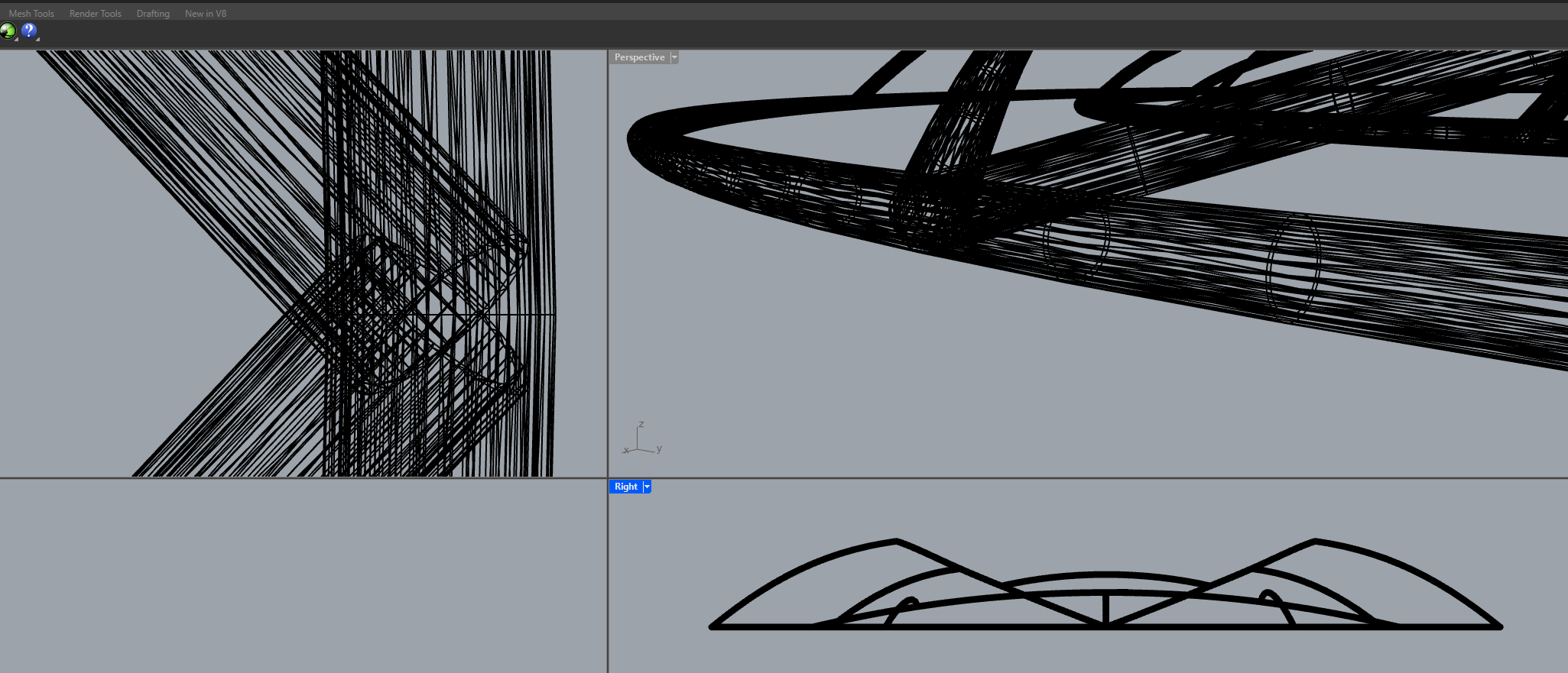
As you will see in the file, I no longer have the beam members obtained from the form-finding process. I tried working exclusively on the beams by passing them through Rhino again, but I can only export them as a 3D mesh (as seen in the image below), rather than as actual 1D centerlines/curves.

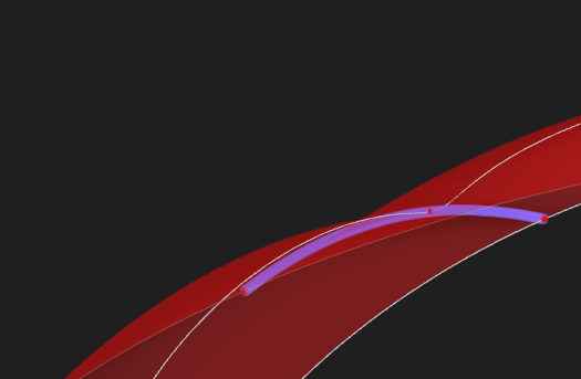
I also attempted to select only the deformed lines directly in RFEM 6, but they seem to be completely dependent on the mesh. When I try to copy and paste them into the new file (where I have the true geometric surface generated from Rhino), the lines appear in their original, undeformed state (without the form-finding shape). Therefore, I am back to square one.

2) Surface continuity
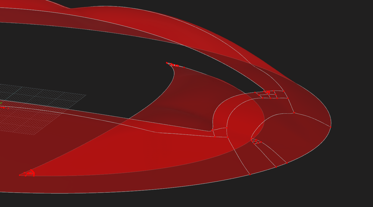
Secondly, as you can see in the screenshot below, the obtained surface is not perfectly continuous; it is divided into multiple patches. I assume this segmentation is due to the export/import conversion process.

I was wondering if it is possible to merge these inaccuracies to obtain true, continuous single surfaces (specifically, one large main surface and two smaller ones). My ultimate goal is to have clean surfaces that I can then manually divide exactly where I want, using the deformed centerlines of the form-found beams.

Do you have any suggestions on how to resolve these issues? Specifically:

Is there an efficient way to export the exact deformed lines/centerlines of the form-found beams (whether passing through Rhino or directly within RFEM)?
Is there a way in RFEM to merge these patches and make the boundary lines disappear to create perfectly continuous geometric surfaces?

Thank you in advance for your help.

Update: I managed to use the undeformed beams as reference lines and project them onto the curved surface using the extrusion command. At this point, only Problem 2 remains.

In RFEM 6 you can’t merge 2 NURBS Surfaces. You may find a solution within Rhino to achieve that. Afterwards you could import the geometry via the STEP format back into RFEM 6.