Is it somehow possible to graphically display the distances of the loads originating from the moving load assistant?
Here, all the displayed loads come from a load model "Operation"; the distances are listed in tabular form in the protocol, but an additional graphical output is also required and I currently cannot provide this using RFEM6 without additional processing using PDF-exchange, etc.
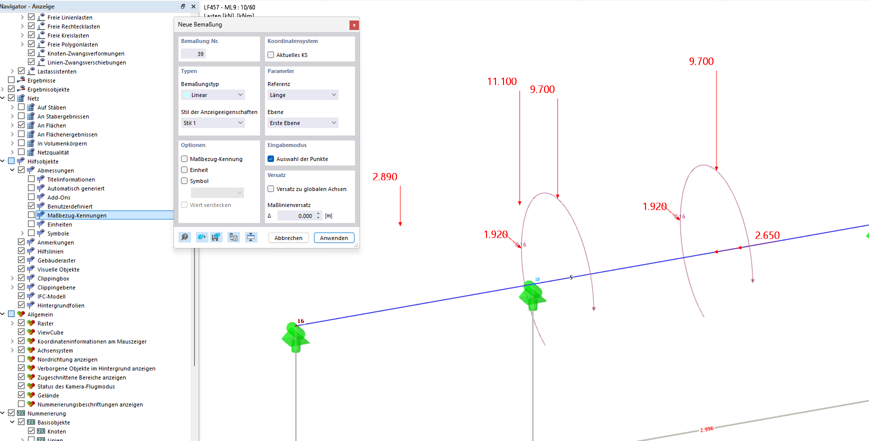
Furthermore, in the above illustration, loads are shown that run parallel to the beam (in the local x-direction). Unfortunately, I cannot manage via the display settings to have these shown closer to their "point of application." In the configuration setting in the view settings that should actually solve this problem, it affects all loads but not the loads in the x-direction. I would rather not make the file publicly accessible but am happy to send it privately.
Best regards,
Nick Böttcher
Hi DeflectionPerfection,
Thank you for your message!
To analyze the problem more precisely, the model would be very helpful:
 Click on File → Save As and choose the following settings to reduce the file size:
To keep it from being publicly available, send it to me via direct message: click on my profile picture or my username → Message.
Best regards
Thomas
Hello Nick,
first of all, thanks for the good point. A representation of the position would be very practical. I tried to implement your suggestion graphically and realized that it becomes quite confusing:
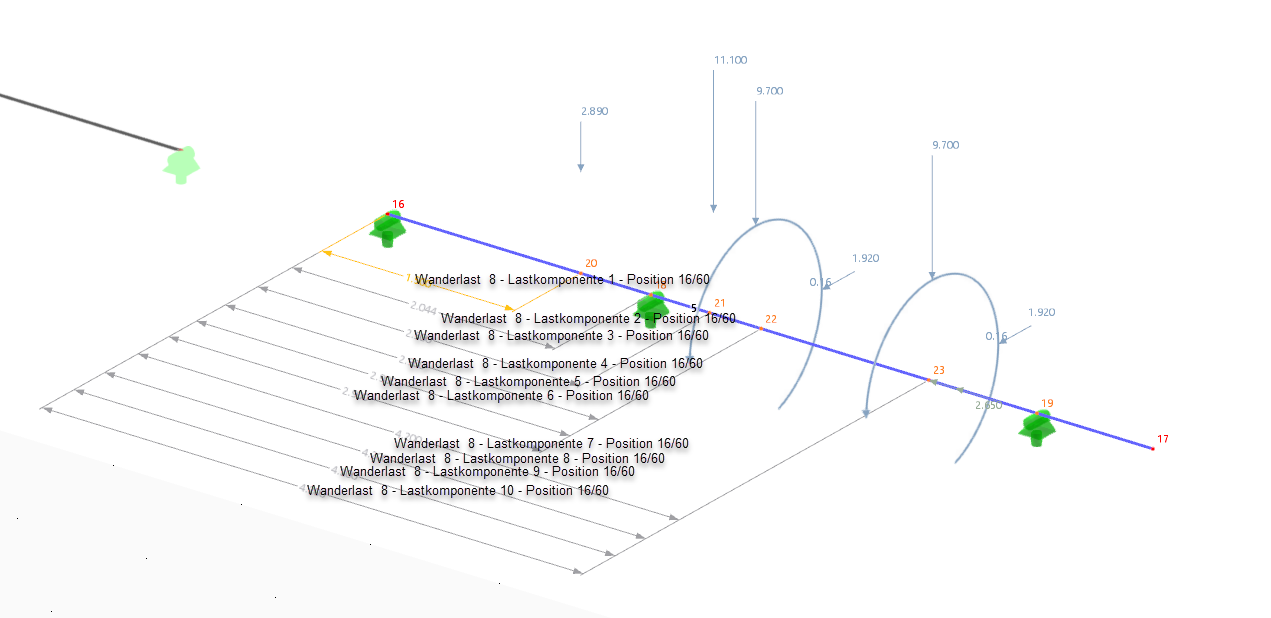
How would you imagine the whole thing, which information should definitely be included?
Best regards
Thomas
Thank you!
That really looks confusing!
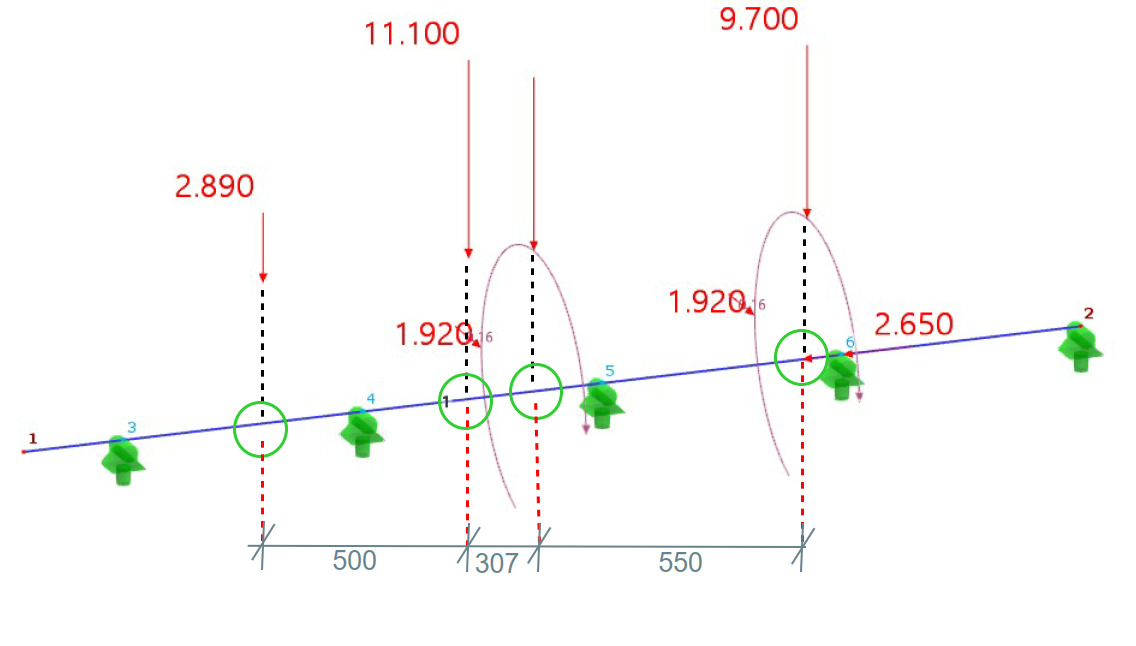
I would prefer a version in which the user can create the dimensioning themselves based on catchable “positions/points.”
I will try to explain this using the following sketch:
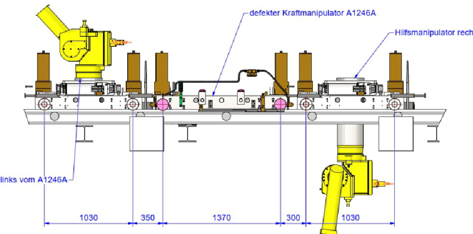
The points on the rod where a load acts in the considered load case/load combination are the ones circled in green; it would be practical to be able to “catch” these points with the command for new linear dimensioning. In the structural analysis I created, several “robot-like” manipulators move along the rail, and for a certain operation, it must be demonstrated or checked at what minimum distance from each other they may operate. Furthermore, there are often purely constructive distances due to the dimensions of these robot-like manipulators, which prevent the wheels from standing tightly next to each other. Therefore, it is particularly important to be able to represent the distances between the respective wheels, which arise as loads from the moving load assistant. This is not an exotic special case for us either; in another structural analysis of a small steel hall, such manipulators also move on two levels, distributing their wheel loads over several rollers stacked above each other. It would likewise have been advantageous there to be able to represent the wheel distances among each other or, if necessary, from wheel load to other nodes.
Hello Nick,
that is a good idea  . I will save it with us like that and hope for a quick implementation.
If you have any further questions, I am happy to assist you.
Best regards
Thomas
1 Like