Hello everyone,
I have a question regarding the principal normal stresses in RFEM. I have modeled a volume model made of steel material, and in the results evaluation, it turned out that the principal normal stresses (Sigma 1, 2 and 3) do not add up. The equivalent stress according to Mises works out according to DIN EN 1993-1-1. The shear stress also works out, and the strains are also below 50 per mille. As mentioned, the principal normal stresses are too high in some areas. The areas are also large, so they are not stress peaks. I do not understand why the principal normal stresses are greater than the equivalent stress according to Mises.
I don’t quite understand the correlation, as this is my first time working with RFEM as a student, and I wanted to ask if this makes sense? And how do I deal with this in connection with GZT proofs according to Eurocode 3? What should be considered during modeling to prevent large principal normal stresses?
Thanks in advance!
Best regards
Michael Chekhovskoy
How do you mean that the stresses do not balance out? Do you mean that the equilibrium of an element is not satisfied? That a stress check is not fulfilled?
The term “not balancing out” is not defined clearly enough.
It would also be great if you could publish the model for this and list the load case as well as the element number, or at least post pictures to illustrate the problem.
Kind regards,
Nick Böttcher
By "not working" it is meant that the stress verification is not fulfilled with the main normal stress. I have uploaded the model here: https://www.dropbox.com/scl/fi/j1dxqy5xi3s84qt1xjthp/Gro-er-K-fig-Rest-der-Br-cken-Nachweis-TML-14-erh-Kopie.rf6?rlkey=agkj64p1q9r7d8ugw9nax0ivb&st=b0895yzd&dl=0. Unfortunately, it was too large to upload here. There is only one load case and the model is loaded only by a surface load.
Volume element 6 should be movable and take up the surface load. The remaining volume elements form a "cage" that is to be welded to the base plate (surface no. 23). Above element 6 is element 10, a lid that is to be screwed with volumes 8 and 9. Actually, in reality it should be a blind hole connection, but since I had problems realizing such a connection in RFEM, I made the connection continuous as beam rods.
Did you remove the results from the model? Our upload limit is currently 25 MB.
More tips: How to Get Quick & Helpful Answers
Cheers
Large Cage Rest of Bridges - Proof TML 14 erh2 - Copy.rf6 (1.7 MB)
Here is the model without results. I forgot to delete these.
2 Likes
Hi Michael1711,
Welcome to the community. Thank you for your model.
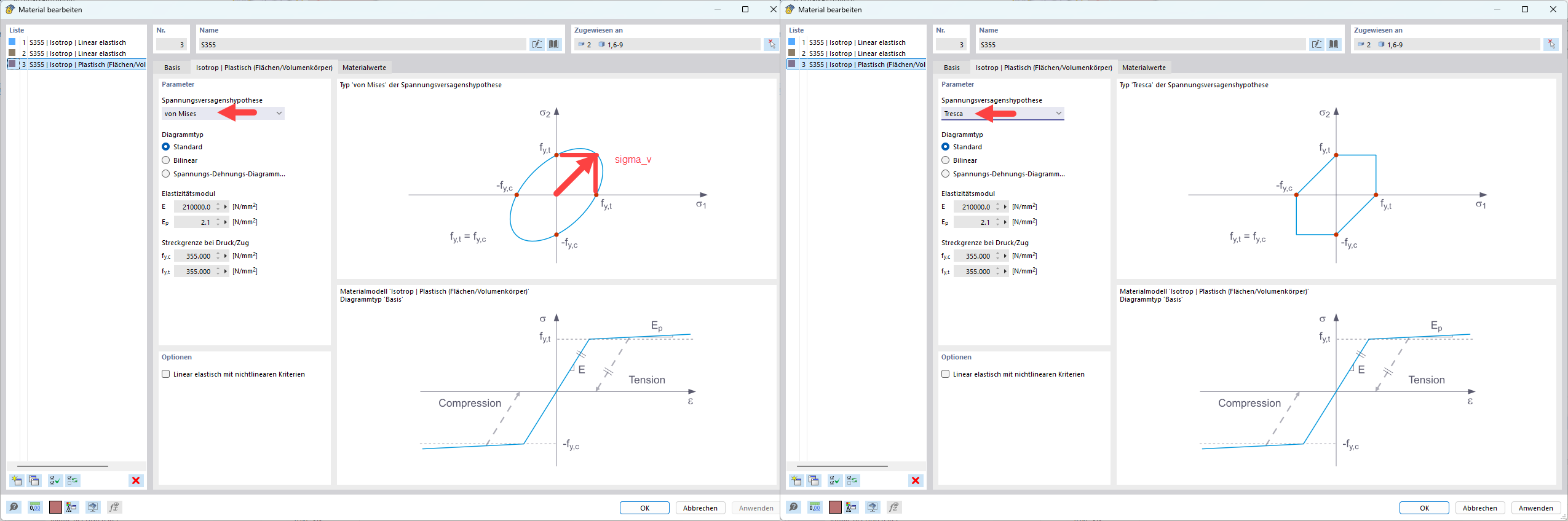
The fact that the principal stresses in nonlinear materials exceed the yield strength according to von Mises is due to the underlying stress failure hypothesis.
What is crucial here is only the equivalent stress – this must not exceed the yield strength. This restriction does not apply to the individual principal stresses.
If you do not want to allow this, you can switch to Tresca instead:
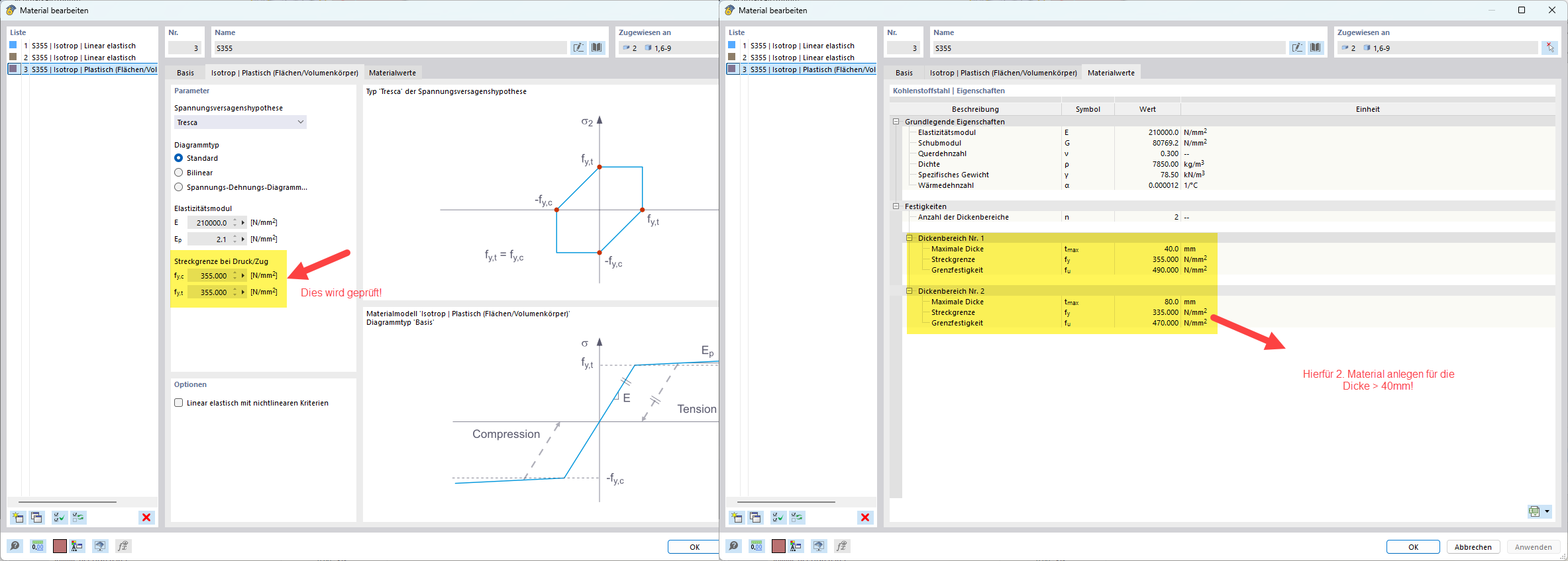
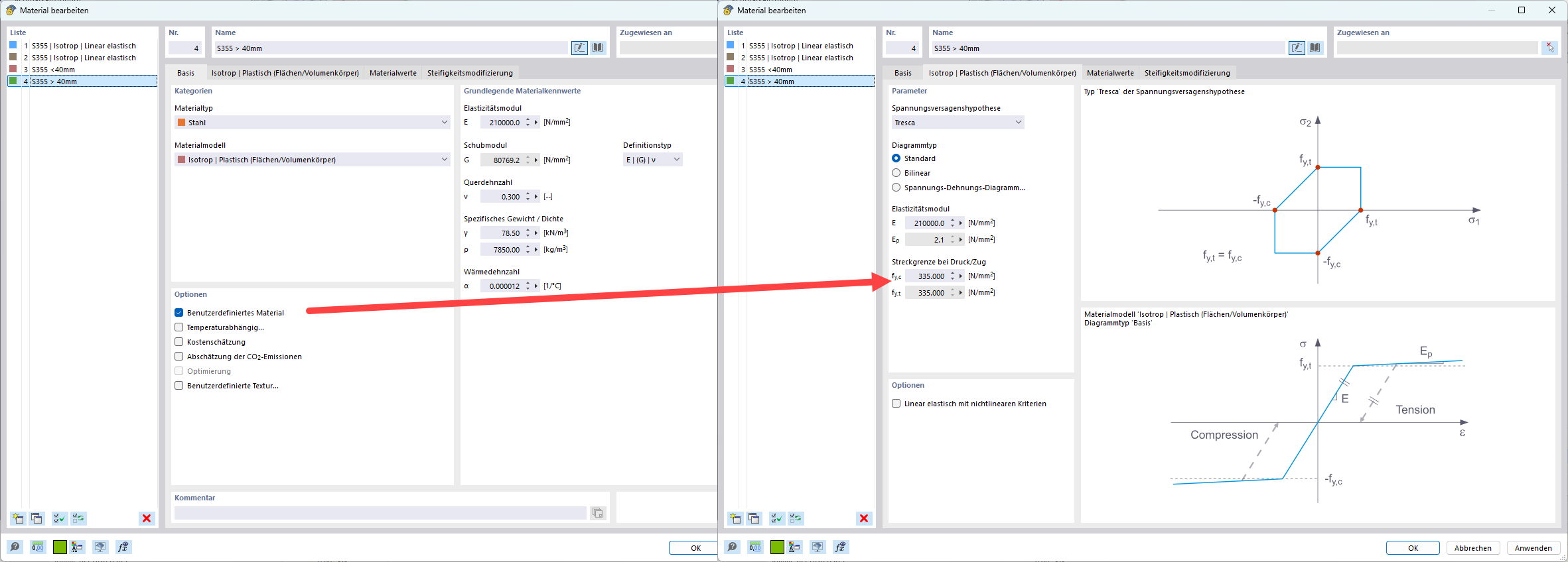
Please also note that the material thickness ranges in plastic materials cannot be automatically checked. For thickness \u003e 40mm, you would need to create a 2nd plastic material so that it can also take the reduced yield strength into account:
Best regards
Stefan Hoffmann
1 Like
Thank you very much for the detailed explanation and help! That has helped me a lot.
Thank you!
Best regards
Michael Chekhovskoy
2 Likes