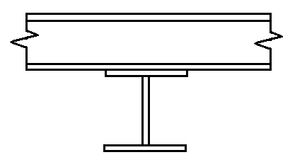
How to model the contact point between two steel beams where a continuous beam 'sits' on top of another beam. The goal is to prevent the bending in the upper continuous beam from creating torsion in the bottom beam.
Hi PSA001,
Thank you for reaching out! ![]()
For your case, you can use a "Scissor Hinge", which should be assigned to both member ends at the same node. This is a great way to model this specific condition.
I recommend checking out this FAQ for more detailed information:
FAQ - Scissor Hinge
If you have any further questions or need more clarification, feel free to ask! I’m happy to help. ![]()
Best regards,
Gerhard Rehm
2 Likes
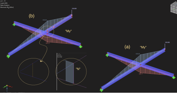
hi, another possibility would be to model both beams in their exact geometrical position and connect them via a rigid beam + conventional hinge with free phy_y on one end of the rigid beam
ive added a figure with both methods, as you can see both yield the same results. (note that the symbol for a hinge isnt visible on the rigid beam here, thats cause im using rfem with paralles on mac and there are visbility problems due an outdated opengl version).
(a) is the scissor hinge with all beams in one z-plane
(b) is the alternative, where the ebams are connected via rigid beam
the pros and cons of the alternative version are in my opinion:
pro:
→ you get the forces transfered between the beams displayed oin the rigid beam, which makes designing the connection easier
→ having the beams in the geometrical right plane often hepls communicating with architects or other planning partners
cons:
→ more modelling work
→ defining the supports must be very precise, or you very quickly generate unwanted moments due to the excentricity (on the other hand sometimes you get to see forces due to rigid supports in different planes, that would be unnoticed otherwise :>)
1 Like
Hi Stefan,
Thank you for providing the additional information! ![]()
You're absolutely right — there are indeed several ways to approach this. Another alternative is using nodal releases. However, I recommend using them only in special cases, as they can introduce complexity.
Additionally, you can also extract forces from a hinge for designing your connections. This can be a valuable approach depending on the specifics of your model.
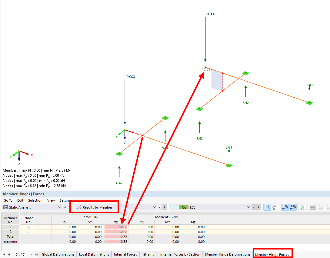
Additionally, you can also extract forces from a hinge
ah, didnt know that. thanks a lot for the info :)
1 Like
Hello! I hope it's not too late for me to join the discussion.
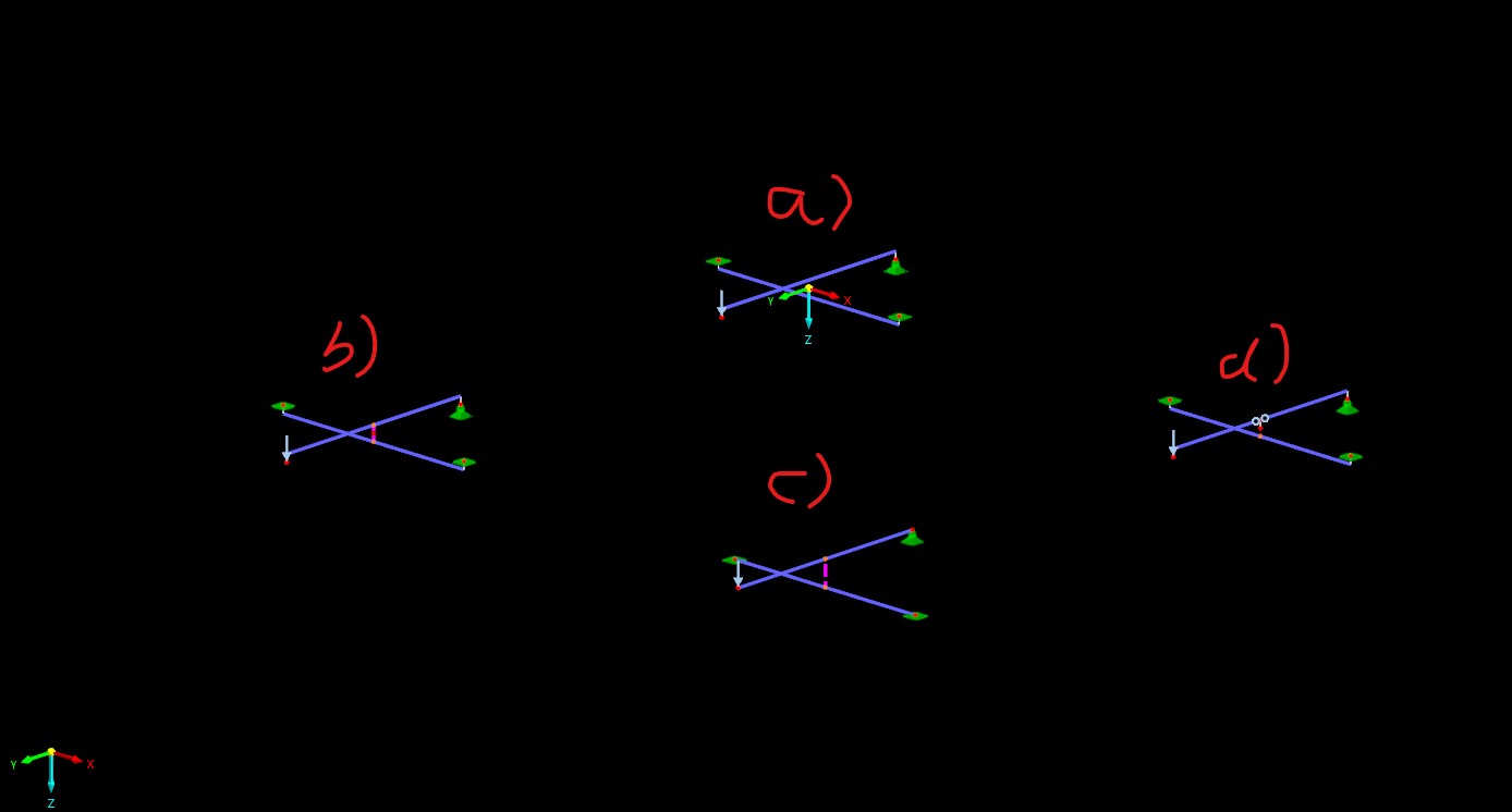
I'm trying to create the most "right" solution possible and for that I have made four smaller versions to test different approaches.
Scissor Hinge.rf6 (1,0 MB)
a) The profiles were simply extruded to the correct height.
b) The profiles were extruded to the correct height and connected with a rigid link.
c) The profiles were modelled directly at the correct height and connected with a rigid link.
d) I tried connecting the bars using a 'scissor hinge', but I’m not sure if I selected the right option.
I would be very interested to hear your opinions.
Hi Maik,
There’s no definitive right or wrong approach here – it all depends on what you're aiming to achieve. ![]()
a)
Personally, I’m not fond of this modeling method. The two members don’t share a common node, which can be a disadvantage when it comes to design aspects such as segmentation for stability and deformation. Of course, you could insert a node to connect them, but this would require working with member sets for the design. The advantage, however, is that you can use scissor hinges to release specific degrees of freedom (DOF).
b)
If you're aiming to consider member eccentricities, this approach works too. As you can see, there is now a restraining moment at node 667. However, personally, I would not opt for this method.
c)
This is my personal favorite, especially when trying to avoid using scissor hinges. I think you may have forgotten to shift down the upper members, as there seems to be a small gap between them.
d)
Everything looks good here. As mentioned in my point above (a), eccentricities are up to you – I won’t judge that choice.
e)
For typical connections where eccentricities aren’t a concern, I would simply use scissor hinges. They can be an efficient solution in this context.