Birdmouth cuts are common at supports of rafters yet I have not yet found how to model and integrate them into a timber-check. Angled cuts and angled compression checks are not sufficiently defined yet to account for a proper contact length and fiber angles. Is there a way to design and integrate them at the moment.
Another issue I have been faceing recently is the design of soffit cuts, rafter tail ends as well as many other, sometimes decorative, cuts that can be applied to a rafters, purlins and all sorts of timber sections. Modeling as a linearly variable section and an absolute offset, but maybe it was not the right direction to go to.
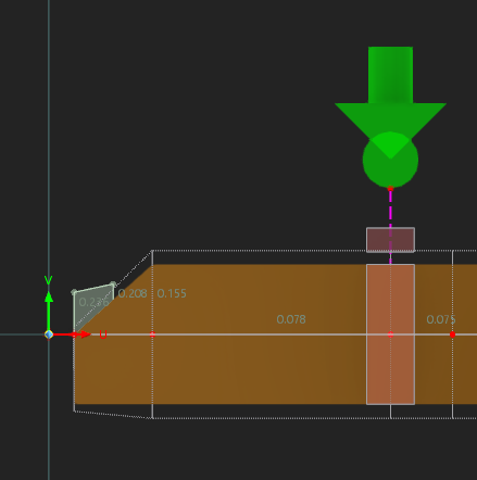
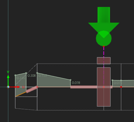
The section appearance :
Checks that fail (angle of fiber is too large, so bending and stability in bending checks failed):
Any guidance would be appreciated, thanks!
Hello,
thank you for your detailed feedback and examples.
Angle alignments relative to the beam orientation on supports are currently not taken into account directly in the timber design. However, for standard rafters, these effects are typically not structurally governing in many practical cases.
Local cross-section reductions can already be modeled, but the grain angles of cuts are currently not considered. I will forward this request to our development department for further evaluation.
Regarding decorative cuts, these can generally be considered similarly to the approach you already described, for example by using locally reduced or variable cross-sections. However, it should first be evaluated whether the cuts are structurally relevant, since decorative reductions often do not significantly influence the structural behavior and therefore may not necessarily need to be included in the analysis.
Best regards,
Eike Mathis Hartmann
Thank you for your answer @eike.hartmann. I am trying to determine how to model this efficiently and obtain a full analysis rather than one with "holes".
Angle alignments seem to be considered since this is what throws of the timber verification in the first place and end up not being able to compute.
In terms of modeling, should I add an excentricity so that the top of the beam matches physically? Or is this an erroneous approach? In some cases, the cut is quite long and could represent a large part of a roof overhang which could lead to a wrong deflection evaluation and even resistance in case of maintenance point loads for instance.
I can forward the model if it is useful for the discussion of the issue.
Thank you for your reply.
To analyze the problem more thoroughly, the model file would be very helpful:
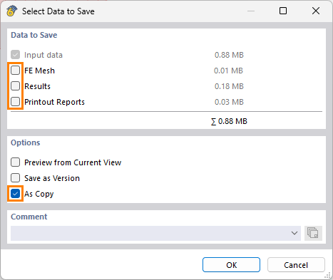
 Click File → Save As and select the following settings to reduce the file size:
Then upload the file here (e.g., *.rf6, *.rs9) – this way, the community can also help find a solution.
 Don’t want to share the file publicly? No problem – send it to me via direct message: Click on my profile picture or username → Message.
1 Like
Thank you Eike. Here's a model I built this morning of a covered walkway. This time, I modeled with a linearly varying section, but no absolute excentricity. I'd be curious too about your guidance regarding using excentricity here so that the top chord of the members match.
260601 - MGI - Passage couvert AVP.rf6 (1,6 Mo)
Thank you for the model, and I apologise for the delayed response.
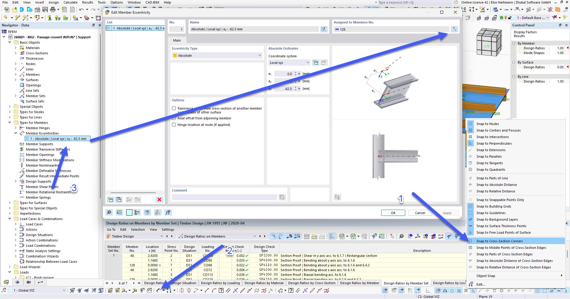
If the cut is relevant, you could add the eccentricities to the model. Personally, I would use the absolute eccentricity and measure the distance between the edges using the snap points (see Image 1). Adding the eccentricities directly at the corresponding dialogue will allow you to apply them to all linear members at once (Image 1-3).
I also noticed, that the Support is used on the transition of the beams while the actual support is further towards the straight beam. You can assign it by setting the node that is used to connect the beam to the supporting structure to the type "On Member".
If you have any additional questions, feel free to ask.
Image 1:
Thank you for the tip on using snapping points.
The support is indeed further down on another node on the beam that has a cantilever as is modeled in the file I attached.
I tried merging the members and it creates a 3-node line that supports the member rather than giving me the option to have the middle node integrated as "on member". Maybe that could be an additional feature of the merge member / merge line function?