Composite steel construction RFEM 6

Hello everyone,
I am currently writing my master's thesis on the topic "Modeling of Composite Bridges in RFEM 6". In doing so, I am comparing different variants of cross-section modeling, and a few questions have come up for me. The cross-section in question is a steel box girder with a reinforced concrete deck slab.

  1. In the first modeling variant, I modeled the steel cross-section in RSECTION and imported it into RFEM 6. I modeled the concrete cross-section directly in RFEM 6 as an isotropic deck slab. When outputting the internal forces, I always receive the internal forces for the steel and concrete cross-sections separately (once for the beam element and once for the surface element). Is it also possible to output total internal forces here?

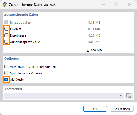
  2. I consider the time-dependent effects of concrete, among other things, with structural modifications. This works very well for the individual load cases. For the load combinations, RFEM does not consider the structural modifications of the load cases. In principle, I can also define a structural modification for a load combination, but I have different effective E-moduli, which is why I have defined different structural modifications. Can multiple structural modifications be assigned to the load combinations?

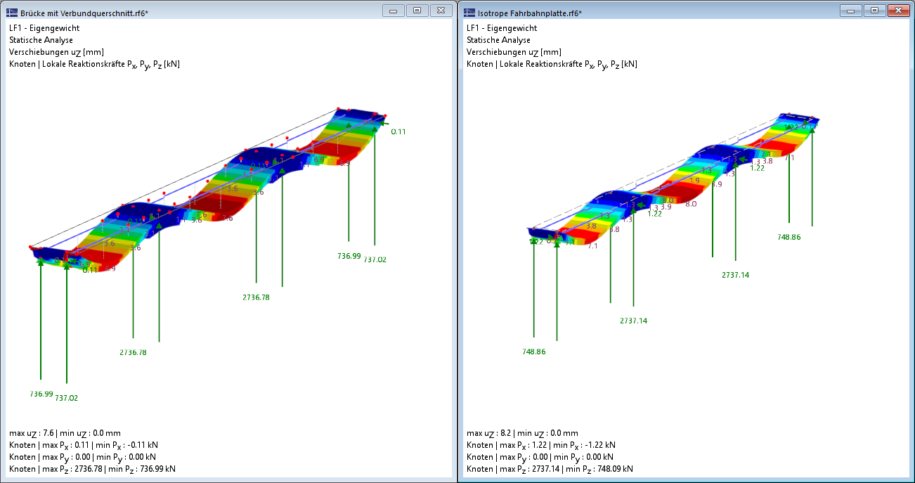
  3. In the second modeling variant, I modeled the entire composite cross-section in RSECTION (concrete and steel cross-section). In the calculation, I get smaller deformations compared to the first variant (approximately 10%), although the internal forces and support reactions match quite accurately. What can this be attributed to?

  4. In the second modeling variant, can I also define the effective E-moduli via structural modifications, or do I have to consider them in RSECTION and then re-import the "new" cross-section into RFEM 6?

  5. In principle, modeling a composite cross-section with the bar type rib is also possible. However, only rectangular solid cross-sections are possible there. Is that correct, or can hollow boxes or I-profiles also be used as rib elements?

Hi Thomas1,

Welcome to the community :waving_hand:
I’m happy to address your points. I can’t promise to answer every question immediately in full detail – but let’s start step by step :blush:


1. Overall Internal Forces

If the objects are modeled separately, each object also receives its own internal forces. There are no overall internal forces in the sense of an automatic summary here.

:backhand_index_pointing_right: One possible approach is to record the results via a result member and sum them there:
https://www.dlubal.com/de/support-und-schulungen/support/faq/005725


2. Behavior of Load and Result Combinations

The described behavior is system-related:

  • In load combinations, individual results are not added.

  • Instead, the result is recalculated under the boundary conditions of the load combination (i.e., a structural modification).

Therefore, you can also define only one structural modification – but of course, this can contain multiple objects.

:puzzle_piece: Alternative:
Addition of results via a result combination.
However, it is absolutely essential to ensure that the superposition principle is observed. Otherwise, results from different structural systems would be superimposed, which is not permitted.

:blue_book: Further information:
https://www.dlubal.com/de/downloads-und-infos/dokumente/online-handbuecher/rfem-6/000261


3. Different Results

The causes of the differences can unfortunately only be clarified based on concrete models. Without these, a reliable statement is not possible.

:right_arrow: Click on FileSave As and select the following settings to reduce the file size:
image

:right_arrow: Then upload the file here (e.g., *.rf6, *.rs9) – so the community can also contribute to the solution.

:owl: Don’t want to share the file publicly? No problem – send it to me via direct message: click on my profile picture or my usernameMessage.


4. Alternative Modeling Approach

For your application, a shell model could be useful:

  • Beams and concrete slab are modeled with surfaces

  • In the end, you can again use a result member to evaluate the internal forces for all objects together


5. Member Type “Rib”

The member type Rib is primarily intended for plate girders, where the lower concrete cross-section is monolithically connected to the concrete slab.

For your described bridge structure, I consider this approach rather not to be effective.


:books: Further Information

By the way, on our website you can already find similar theses that might be interesting for you:
https://www.dlubal.com/de/bildung/studenten-und-schulen/abschlussarbeiten?q=verbundbau\u0026f=\_

If you want, we can also take a look at your model together – just let me know :blush:

Best regards
Stefan Hoffmann

Hello Mr. Hoffmann,

thank you very much for your response. You have been very helpful to me. Attached I have included the two RFEM files with the different modeling variants and differing deformations.
Bridge with composite cross-section.rf6 (1.6 MB)
Isotropic roadway slab.rf6 (1.1 MB)

In the mid-span in load combination LC2 1.35xLF1 + 1.5xLF2, I have about 10% more deformation in the model with the isotropic roadway slab.

Thank you very much in advance

Best regards

Hi Thomas1,

thank you very much for your feedback.

To investigate differences, I would first reduce the models so that in the file Bridge with composite cross-section no additional area is present (which you do represent in the cross-section) and in the comparison model Isotropic roadway slab the area is present. Load case 1 then looks similar without the extra 10 kN/m² that you apply:

image

Now it is not quite clear to me why you also model an area with stiffness again in the file Bridge with composite cross-section. Is there a reason for that?

Best regards
Stefan Hoffmann

Hello Mr. Hoffmann,

Thank you very much. I have modeled the additional area to account for any effects from the load-bearing capacity in the transverse direction. The area has a density of zero, so it should not be relevant for the internal forces either.
From your perspective, could I also omit the area?

Best regards

Hi Thomas1,

thank you for your feedback. So you want to distribute the loads with it? Then you should try a load transfer surface, because the other surface otherwise adds stiffness to the system when you compare the two models.

You can find a webinar here:

https://www.dlubal.com/de/support-und-schulungen/schulungen/videos/005343

Best regards
Stefan Hoffmann