Hi Dlubal team,
I’m working with the Member Type Anchor in RFEM 6 (Geotechnical Analysis add-on) for the first time, and I would really appreciate some clarification on how to use it.
My project case is:
-
a concrete foundation slab
-
the anchor passes through the slab
-
then has a free length in the soil
-
and then a bonded length in soil/rock
The stabilising action of the foundation relies on the locked-in anchor tension. Without the anchor, the slab would overturn.
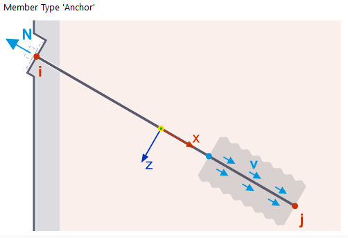
The manual image shows the anchor with an arrow N at the head, which I understand represents the prestress / lock-off force:
I’ve gone through the online manual page here:
and also browsed the downloadable models here (filtered to Geotechnics):
but I couldn’t find an example model using the Anchor member, and I also didn’t find any knowledge-base articles specifically focused on anchors (apart from the manual section mentioned above). That’s why I’m hoping for a bit of additional guidance here — and hopefully the thread will also help others using anchors for the first time.
- Where and how should the prestress be applied?
In the above image I see the N with the arrow outwards indicating the initial tension/prestress of the anchor. In the Anchor member dialog, I cannot see a field for entering a prestress value. Is it done as an applied nodal load? I know there is prestress for concrete members, but I assume this is different?
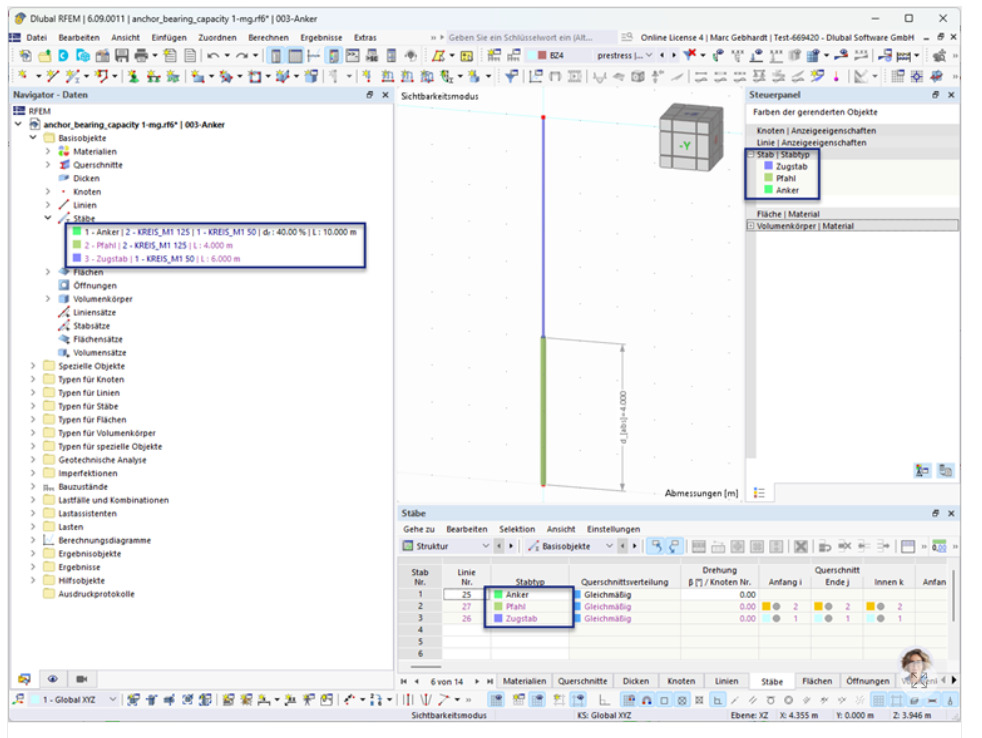
From the above screenshot from Members | Basic Objects | Structure | RFEM 6 | Geotechnical Analysis it looks like there is a load case prestress.
- Clamping effect on the slab
Conceptually, the anchor is jacked outward, then released, so there’s essentially a clamping force between the anchor head (which in my case is transmitted through the foundation/slab surface and into the ground through compression, and then through the bond length.
If the anchor head is connected to the slab, and the prestress is kept active in the relevant load combinations:
-
does RFEM treat this as locked-in tension, and
-
does it correctly produce the associated compressive reaction in the slab and soil (i.e., the stabilising clamping force)?
This is important for my model, because the slab stability depends on that permanent anchor force. How do I have the anchor linked into the slab? I know for the soil solid I would have the anchor member line as an integrated object in solid for independent mesh.
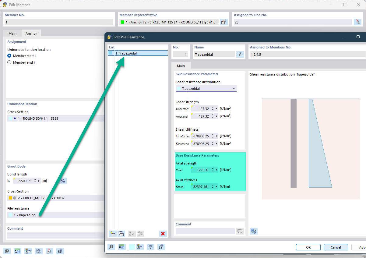
- Axial load transfer at the bonded end (base resistance)
Just double-checking something regarding axial strength and stiffness at the bottom of the bonded length.
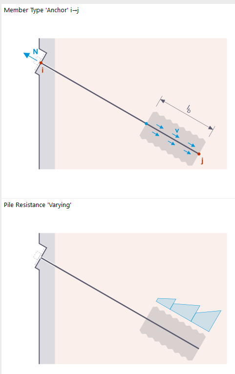
In the manual image, unlike pile elements, there is no arrow shown at the anchor tip. That made me wonder:
-
does the Anchor member consider axial load transfer at the bottom (tip resistance),
-
or is load transfer assumed purely along the bonded length (skin friction only)?
Is the “pile-tip” style resistance automatically not counted for Anchor members, or is it still part of the calculation unless explicitly set to zero?
For clarity, in my case I plan to set the pile resistance at the tip to zero anyway — but I would like to understand what RFEM is doing conceptually.
- Anchor head geometry and load application
Does RFEM assume any standard bearing-plate/head geometry at the slab? can this be modified to suit the ground anchor we use? Does the geometry of the head affect the stress distribution or does it just come from a plate? I note that the image above showing the N and the arrow has the faint outline of the head.
For context: I normally design rock/ground anchors manually (bond length, free length, capacities, etc.) and design the foundation concrete slab using strut-and-tie. My goal here is to use RFEM as a refined verification tool to better understand load transfer, slab stresses, and interaction with the surrounding soil.
Thanks very much in advance. Any explanations or references would be very welcome, and I suspect other users may benefit as well.
Also I know that its meant to be one post per question but I though having all this in one post would be appropriate as its all to do with the member type Anchors and keeps it nice and tidy in one place for anybody else who wants to know more about this, as there’s not to much guidance in the knowledge articles.
Kind regards,
Samuel