Hello @amirarmia,
currently, tendon elements in RFEM 6 can already be considered in the structural analysis if the tendon members are located within a member or surface.
However, please note that a dedicated prestressing design is still under development and therefore not yet available at the moment.
For modeling tendon members, the following workflow is recommended:
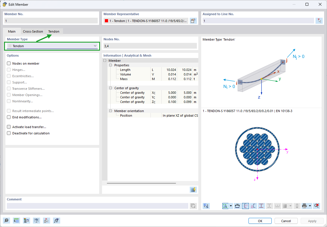
Create the tendon as a dedicated member
When creating the member, select the member type “Tendon” in the member basic settings.
Select a prestressing steel cross-section
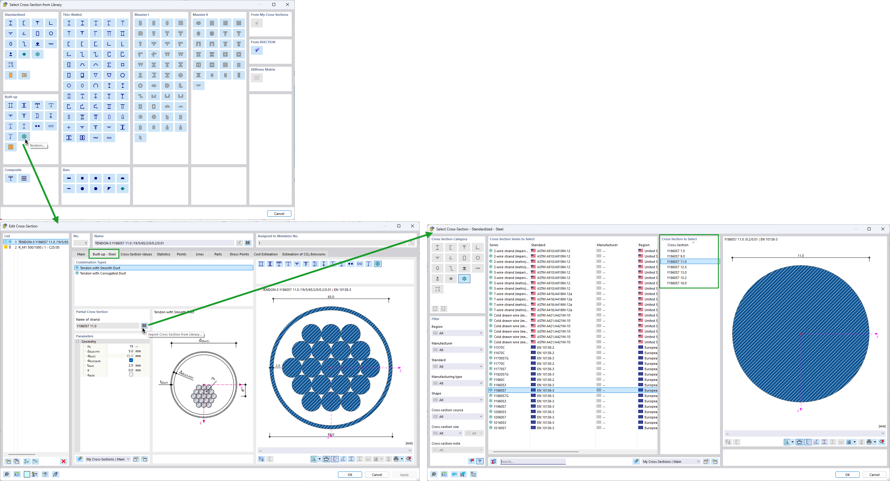
Prestressing tendon cross-sections can be found in:
Cross-Section Library → Built-Up → Tendons
These predefined tendon cross-sections already contain strand definitions.
For example: Y1860S7 11.0, where 11.0 represents the strand diameter (in mm).
Model compatibility between beam and tendon
For the tendon member to work correctly together with the beam member, the following points are important:
Therefore, for a simple single-span beam with one tendon, you would typically create:
Tendon geometry / profile
The tendon profile itself is currently modeled geometrically through the tendon member shape and node arrangement.
At the moment, tendon geometries can be created using:
In addition, further improvements regarding automatic tendon geometry generation are currently under development.
For your thesis topic in general:
In practical bridge engineering, tendon profiles are usually determined based on:
-
bending moment distribution,
-
serviceability requirements,
-
allowable concrete stresses,
-
construction stages,
-
and tendon eccentricity requirements.
Typically, parabolic tendon profiles are used for simply supported beams, while more complex continuous bridge systems often require segmented or spline-based tendon layouts.
The tendon profile itself is currently modeled geometrically through the tendon member shape and node arrangement. At the moment, tendon geometries can be created using: straight lines, parabolic curves, and NURBS-based geometries.
In addition, further improvements regarding automatic tendon geometry generation are currently under development.
I will attach some screenshots showing the tendon definition workflow in RFEM 6. 
I hope this information helps you with your thesis. If you have any further questions, I would be happy to help.
Tendon Example.rf6 (1,1 MB)