Hello everyone,
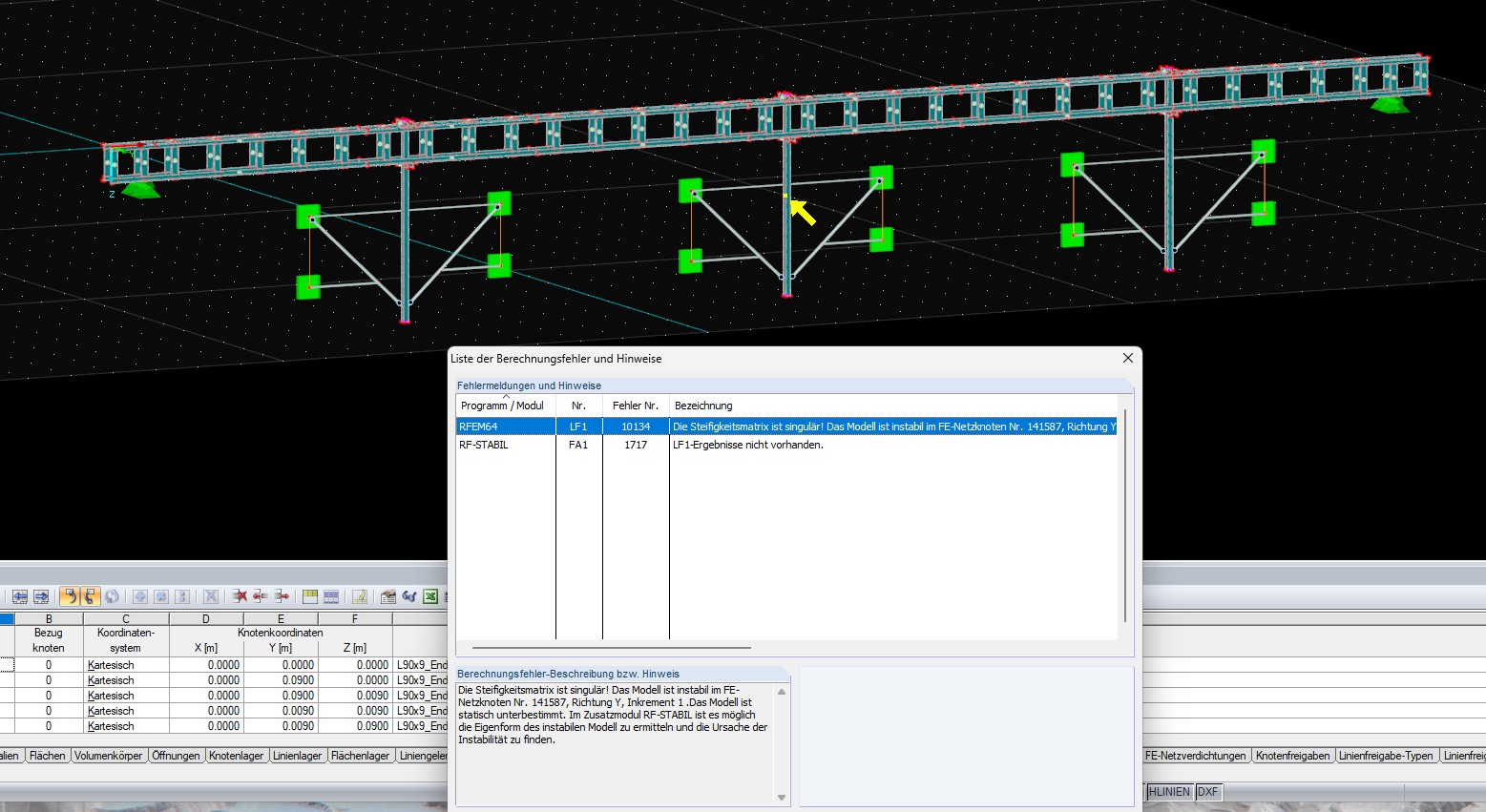
I am currently a student at the University of Duisburg-Essen and am writing my master's thesis. Attached is the RFEM5 file with the created model. The model mainly consists of solid bodies. To check the modeling, I tried to calculate the model with the load case self-weight. I receive error message No. 10134. The model is supposed to be unstable at a FE mesh node and the model is statically underdetermined. I do not know what I can do at this point. Attached are the RFEM5 file (due to the file size I deleted the FE mesh) and an image of the model with the error message.
I ask for help.
Modeling.rf5 (3.0 MB)
Best regards
Kamaljit Singh Tatla
Hello and welcome to the Dlubal Community! 
Nice to have you reach out to us.
To help you with your concern, I recommend reading this FAQ. It covers the most common causes of unstable models and offers useful solutions:
Common Causes of Unstable Models
Modeling with Solid Bodies
As I see, you have modeled the entire model with solid bodies. I wonder if that really makes sense in your case.
In many cases, a surface model may be sufficient (possibly even a beam model) and saves a lot of computing time. It might be worth checking again here whether a surface model would be the better choice.
Problems with Contact Conditions
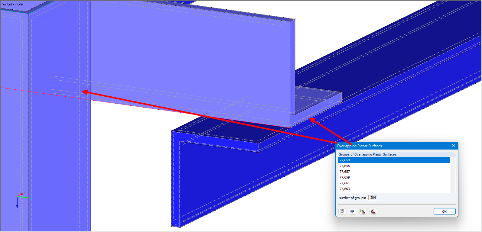
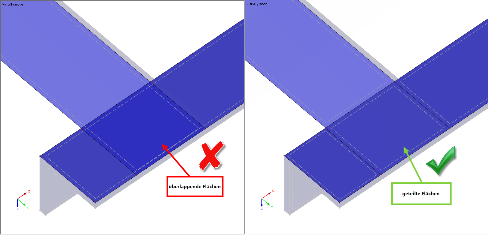
Another issue I noticed: Your contact conditions are currently modeled incorrectly. This causes the meshing not to work properly. There are overlapping surfaces that should not exist like this.
Rigid Contact
If you are modeling a rigid contact, then the same surface must be integrated in both volumes to achieve correct results.
I hope these tips help you further!
1 Like
Thank you very much for your response, Gerhard!
I have followed your suggestions and made progress :)
I am currently also trying to model the system as a surface model and have questions regarding this. How should surfaces that lie one behind the other or on top of each other be considered so that I have correct contact conditions? And how can I correctly model an L-profile as a surface?
Thank you very much.
Best regards,
Kamaljit Singh Tatla
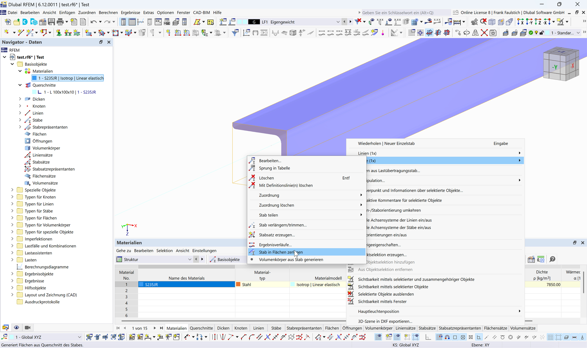
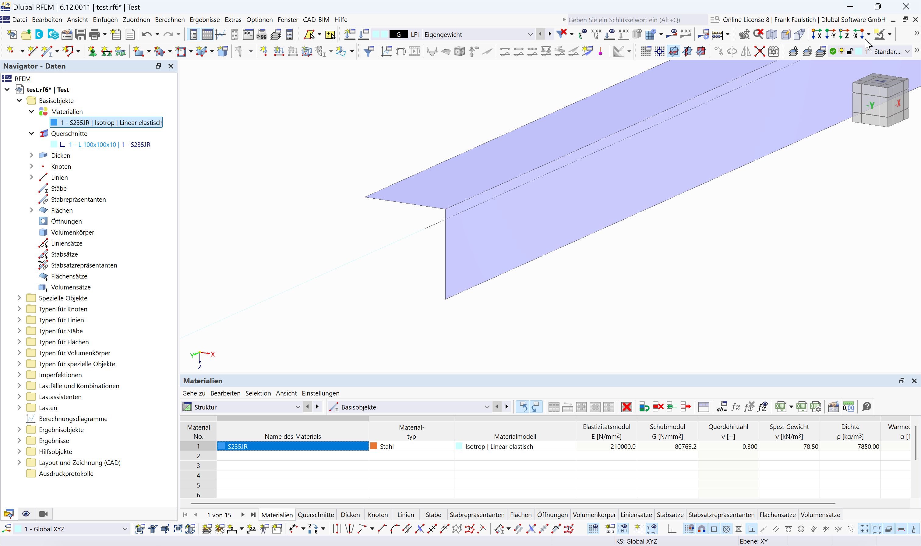
I'll start with the last question. In surface models, the mid-surfaces are always modeled. You can do this manually. You can also make your life easier by first modeling the L-profile as a beam.
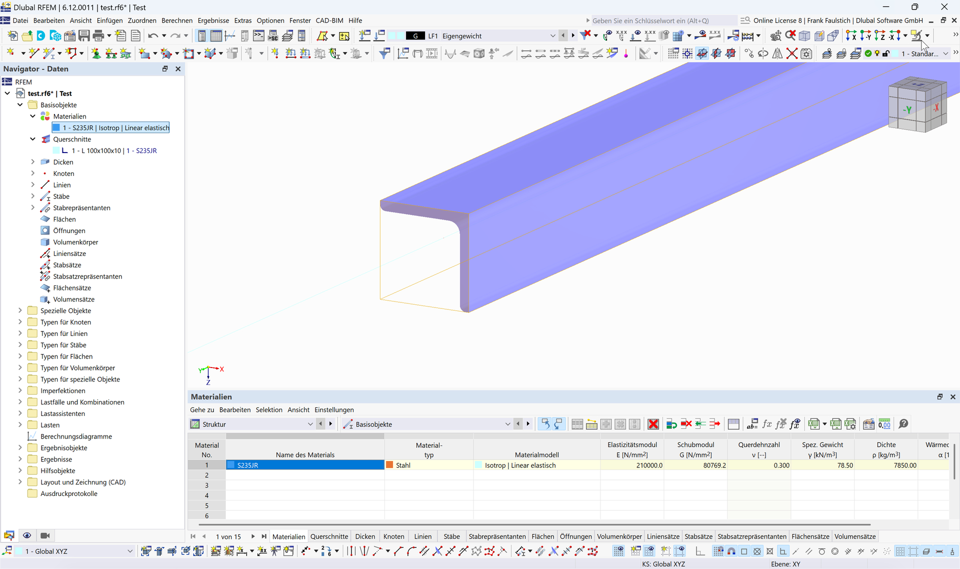
Then you can convert the beam into surfaces.
Regarding the contact:
Model the two contact surfaces with a gap.
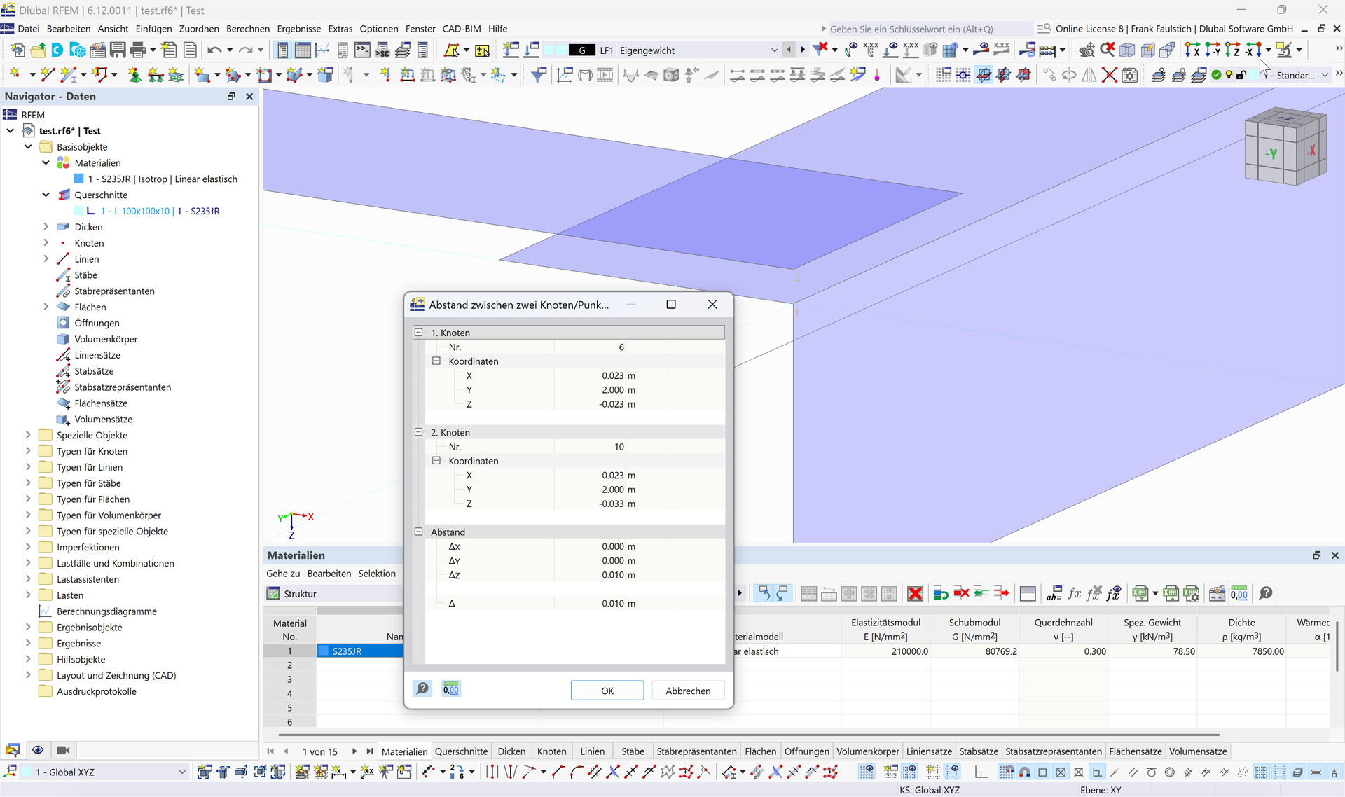
The gap results from half the thickness of the first surface plus half the thickness of the second surface.
Then define the surface contact.
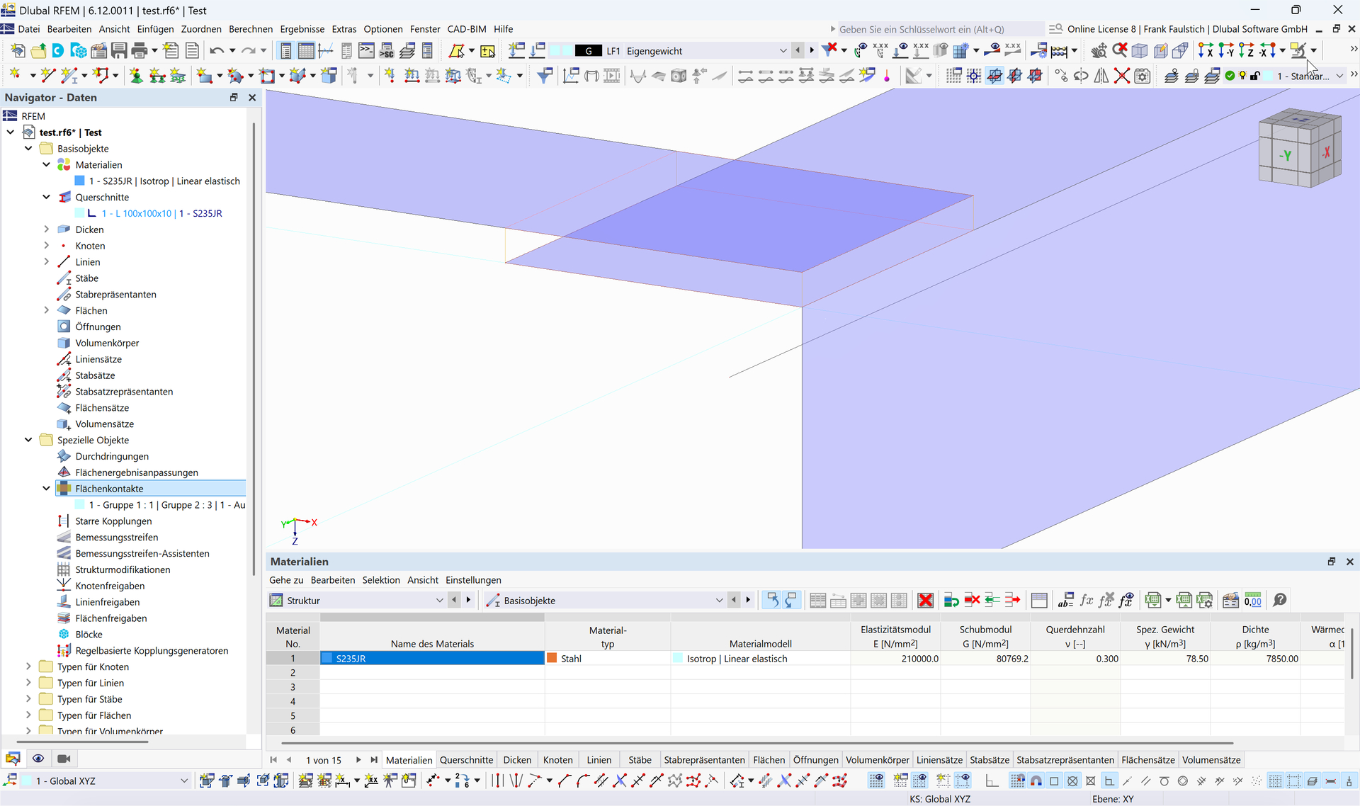
You can find more about surface contact here:
Best regards
Frank
1 Like
Thank you very much for your response. I have understood the procedure that the modeling of a surface model is always done via the mid-surfaces. However, I still have a general question regarding the modeling. To possibly better understand my question, see the attachment (image file: "Modeling_SurfaceModel_CrossSectionView"). The red line represents the mid-surface of an L90x9, the green line the mid-surface of a flat steel 150x9, and the yellow line the mid-surface of a flat steel 100x9. The mid-surfaces of the L90x9 (red line) and the flat steel 150x9 (green line) share a common point through which a connection is established. The mid-surfaces of the L90x9 (red line) and the flat steel 100x9 (yellow line) do not have a common point, therefore there is no connection between them. The two components must be connected via a common node. However, I cannot move the node of the L90x9 (red line) to the node of the flat steel 100x9 (yellow line), because otherwise part of the L90x9 would lie inside the flat steel 100x9. How can I proceed here, or is there also a possibility to establish a correct connection in this case? Thank you.
Best regards
Kamaljit Singh Tatla
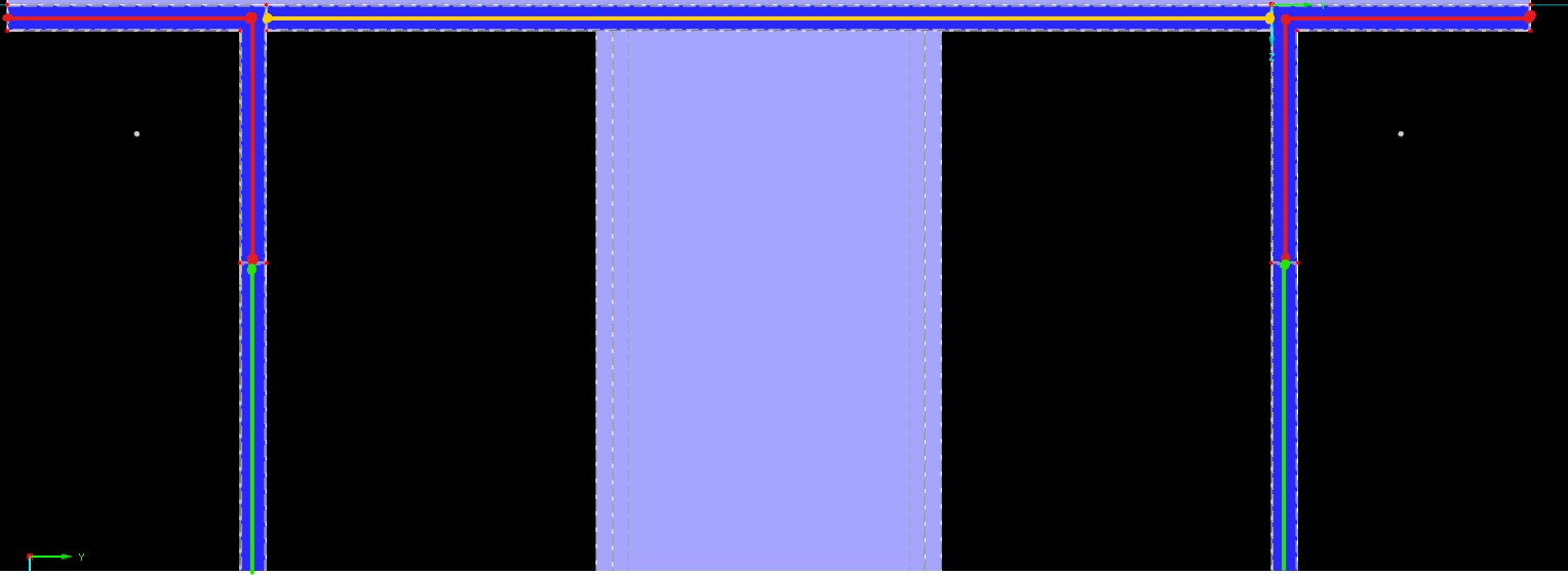
Usually, the node of the yellow area is moved to the corner node of the angle. This makes the yellow area slightly larger than in reality. In most cases, however, this is sufficiently accurate.
If more precise modeling is required, which is not necessary in your example, then a line coupling can be used.
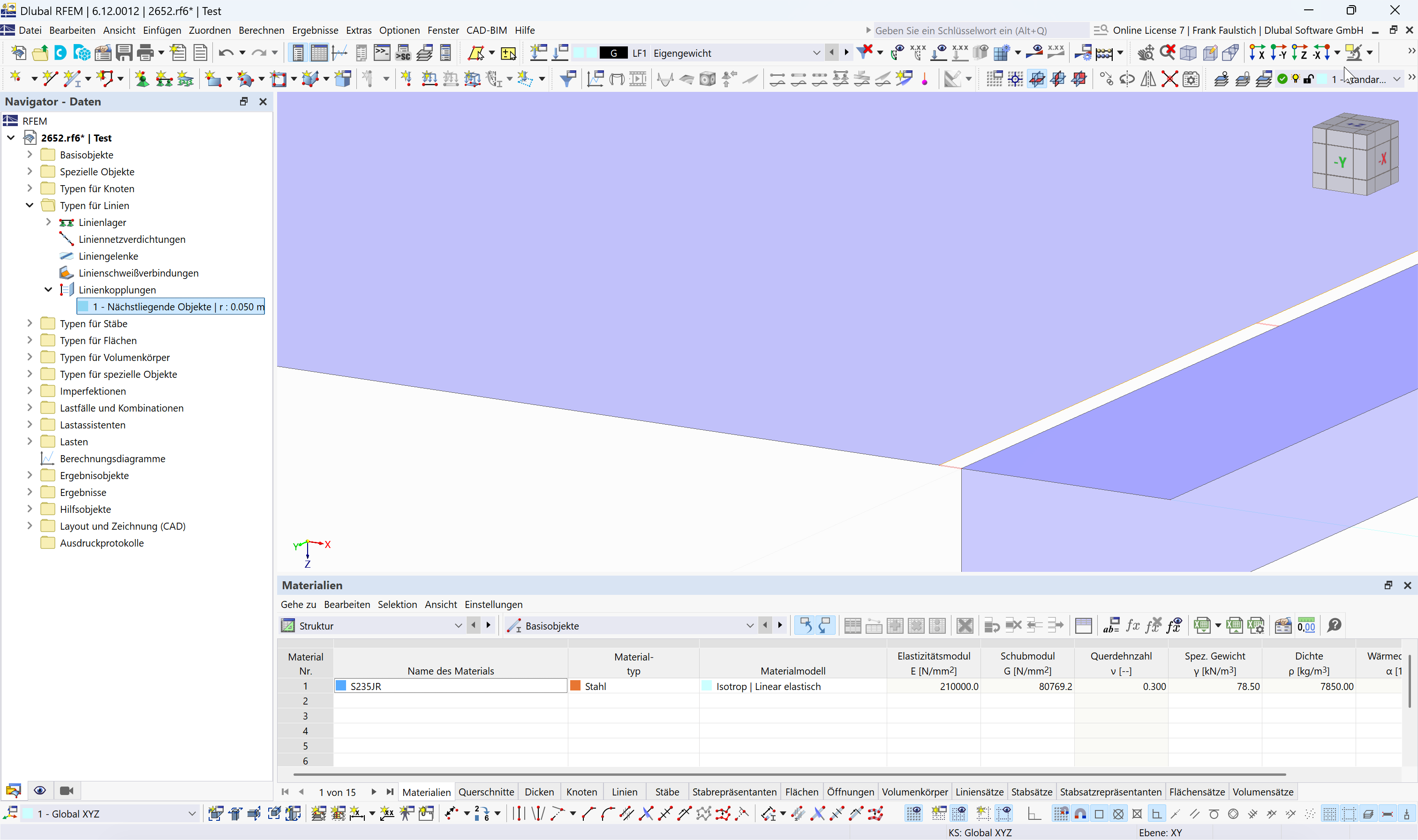
2652.rf6 (882.7 KB)
The example file shows both options.
Best regards
Frank
Thank you very much for your help :)
Best regards
Kamaljit Singh Tatla
1 Like