Embedded Beam in RFEM 6

Hello everyone,

I am trying to model a embedded beam in RFEM 6 as part of my studies, but I am not fully satisfied with the result.

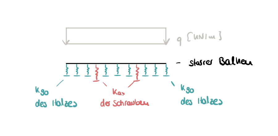
The beam should be modeled in 2-D and initially be rigid. The model itself is supposed to represent a pressure plate on a wooden beam with screw reinforcement. Here, the wooden beam and the screws should be symbolized by springs. The beam is loaded with a line load. For illustration, I have attached a hand sketch of the model. The dimensions and the magnitude of the load are secondary for now, as it is about the principle.

Embedded Beam

The model only allows me to apply a rod support without causing error messages. Shouldn't I actually be able to apply a line support for the wood and a node support for the screws, and the beam would still be supported? However, when I try this, I get the warning “Line support cannot be assigned to line no. 1, which is not connected to any surface.”

The wood and the screws should also exhibit tri- or bilinear behavior, which I believe I can select in the line supports by choosing “Diagram” under “Nonlinearity” and then reflecting the curve based on displacement and force. If I am wrong, please correct me.

I do not have this option with the rod support, as it only offers the choice of “failure,” and I also do not want to influence the “nonlinearity” of the rod, since it is about the wood and the screws as springs.

So, to represent my model and be able to read out the resulting forces in the springs, I have to work with line supports and not with the rod support, right? Or is there another possibility?

I would be very happy if you could help me with my problem and, ideally, provide a model as described for illustration so that I can better understand where my mistake lies.

Thank you very much in advance.

Hi Nicele,

Welcome to the community! :waving_hand:

Line supports can only be applied in RFEM on lines in connection with surfaces. Therefore, in your case, only rod supports are available to you.

As you correctly describe, rod supports do not support all desired nonlinearities. In such situations, you can often achieve your goal with line releases. Feel free to take a look at these posts from the RFEM 5 Knowledge Base – the procedure is very similar in RFEM 6:

The articles show typical application cases for connectors and line releases that might correspond to your project.

Unfortunately, we cannot provide you with a finished example model. But: We are happy to support you directly with your model – just post relevant screenshots, a brief description, or upload the file. :slightly_smiling_face:

Best regards
Stefan Hoffmann

Thank you very much for your response!

For my understanding: In order to obtain the case from the image above, I still have to support the bar via the bar support to get results. Are the required spring stiffnesses now set as low as possible in the support so that a calculation can take place, and the actual spring stiffnesses are entered via the line releases, or must the bar support already have the spring stiffnesses and the nonlinearity is only taken into account in the line releases via the diagrams?

I have attached my current file. Here the bar is rigidly designed and the bar support currently only has arbitrary spring stiffnesses for testing. The compressive load is also currently chosen arbitrarily.

Is this the correct approach if I want to model the model from the previous image, assuming the line releases would now be entered correctly? And would the currently missing bolts then be entered via the "node releases" or differently?

Thank you again in advance for looking at the model and for your help.

Balken_Federlagerung.rf6 (1000.3 KB)

Hi Nicele,

Thank you for your feedback! :blush:

Please do not use a rigid bar for such analyses.
A better choice is a bar with the bar type stiffness:

:right_arrow: Online manual:
https://www.dlubal.com/de/downloads-und-infos/dokumente/online-handbuecher/rfem-6/004141


This is what the setup means:

  1. Below the bar, create a fictitiously rigid surface,
    with your bar serving as the centerline of the surface.

  2. Support this surface rigidly to simulate a full fixed support.

  3. The support or connection of the bar between the bar and the surface can then be modeled via
    line releases and thus via springs.

This way, you get a realistic and controllable modeling of the compliances.
If anything is still unclear, feel free to contact me! :speech_balloon:

Balken_Federlagerung_mod.rf6 (1.0 MB)

Best regards
Stefan Hoffmann