Hello everyone! I am writing a thesis on the topic of "curved insulated glazing." For this, I would also like to investigate a way to calculate a model with RFEM 6. During my research, I came across the Dlubal webinar "Calculation of a laminated glass pane in RFEM 6." https://www.youtube.com/watch?v=inZNeuPq8ys
To verify the results, in the next step I compared the results from RFEM 6 with those from Uniglas Global on a flat pane. The model was created exactly as in the webinar. The stresses calculated with RFEM 6 were about 30% higher. What causes this deviation? Is it possible to model insulated glass panes with RFEM 6 according to the requirements of DIN 18008?
The following boundary conditions apply to the test:
l = 1.83 m b = 1.592 m
Setup
6 mm (glass)
14 mm (IGU spacer)
6 mm (glass)
Gas pressure 1.01 bar, temperature 19 °C
Reference Uniglas Global
Summer 1.96 N/mm²
Winter 3.03 N/mm²
RFEM 6
Summer 2.535 N/mm²
Winter 3.643 N/mm²
Thank you very much for the help.
Hi @Immanuel.Cordes,
exactly, the video describes how to manually model an insulating glass pane.
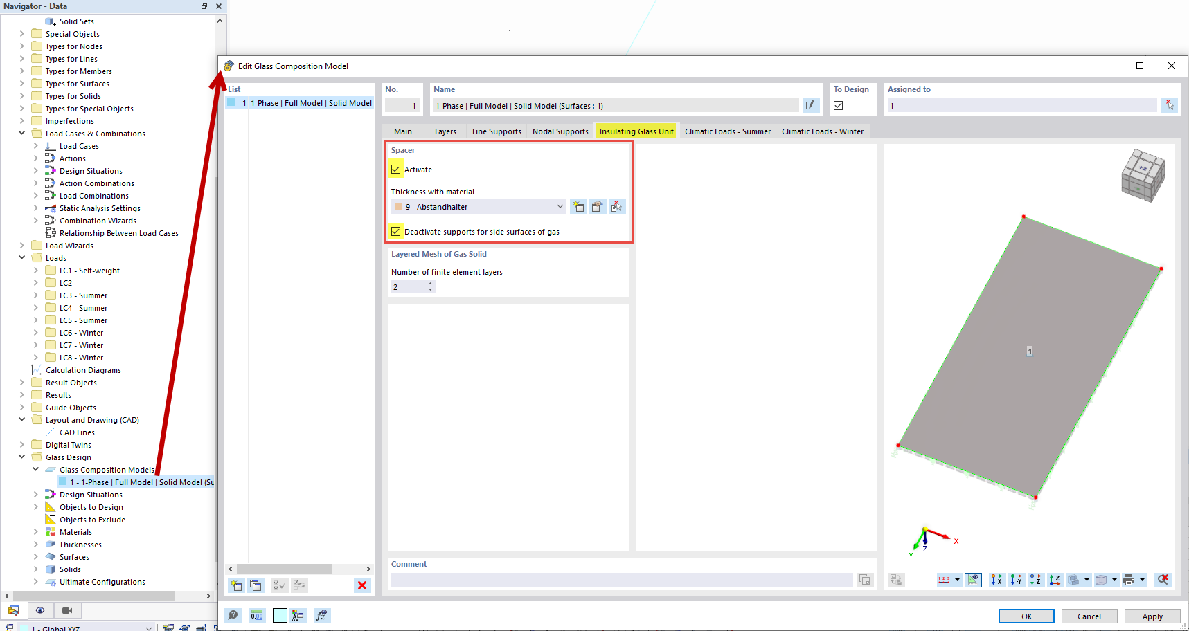
From version 6.13.0008 onwards, the possibility has also been implemented to automatically create and dimension the insulating glass unit with associated climate loads.
I am attaching a small example for you.
Example_IGU.rf6 (1.0 MB)
Here you can compare the modeling with your file.
Because I strongly suspect that the differences in the results are due to differences in the modeling. In addition, different materials, support conditions, or the calculation theory (first-order; third-order) could also be the reason for the deviations.
However, this is difficult to assess without the calculation file. Therefore, I would ask you to compare your file based on my hints and, if deviations still occur, to share your file here.
Best regards
Hello Mr. Lex,
Thank you very much for your feedback. At first glance, the model in your file looks completely different from the model shown in the video. The video does not feature any line hinges, and the surface of the edge connection is not supported in the middle in the local y-direction, etc.
The model in the video is much simpler to create. Therefore, this model is very interesting to me. I think I have modeled everything correctly. It would be great if you could take a look at the file and provide feedback on why I have such large deviations.
Klimalasten Test.rf6 (1.2 MB)
Thirdly, I determined the load analytically according to DIN 18008 and applied it to a glass pane in RFEM 6 according to Th. III Ord. I achieved a deviation of only 1% from the reference values. So these two methods yielded very similar results.
Thank you very much for your effort.
Best regards
Immanuel Cordes
Hello @Immanuel.Cordes,
yes, the edge bond with so-called auxiliary supports is depicted in the model. However, these are generated automatically by the program 
You can also change this by adjusting the settings for the insulating glass.
I would also be happy to take a look at your file.
One piece of information would still be interesting: What initial values for the climate loads are assumed for the calculation?
For me, the initial values are interesting.
Because due to the sealed insulating glass unit, the resulting loads on the outer and inner pane are automatically distributed correctly based on the stiffness of the pane.
Best regards
Ulrich Lex
Hello Mr. Lex,
Thank you very much for the hint. If there is a video about the "Glass Design" addon in RFEM 6 regarding insulating glass panes, that would be very helpful. At first glance, I have only found videos concerning the modeling of laminated glass.
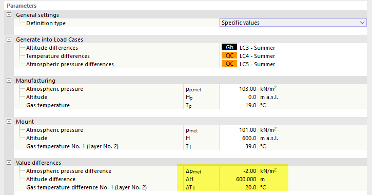
The following climate loads were used:
Altitude difference: ΔH = -40 m → -0.48 kN/m²
Winter
ΔT = -25 K
Δpmet = 4.0 kN/m²
Summer
ΔT = 20 K
Δpmet = -2.0 kN/m²
Gas temperature 19 °C
Gas pressure 1.01 bar
Best regards
Immanuel Cordes
Hello @Immanuel.Cordes,
Since we only recently published this, unfortunately there is no video available yet. However, the webinar ‘Calculation of an Insulating Glass Pane’, at the end of March, will cover this topic and demonstrate the modeling procedure.
Regarding your file, there is actually nothing to criticize in terms of modeling or loading.
The only thing you might want to consider is the edge seal.
This was connected to the glass pane without line hinges. As a result, there is a certain stiffness at the edge of the glass pane.
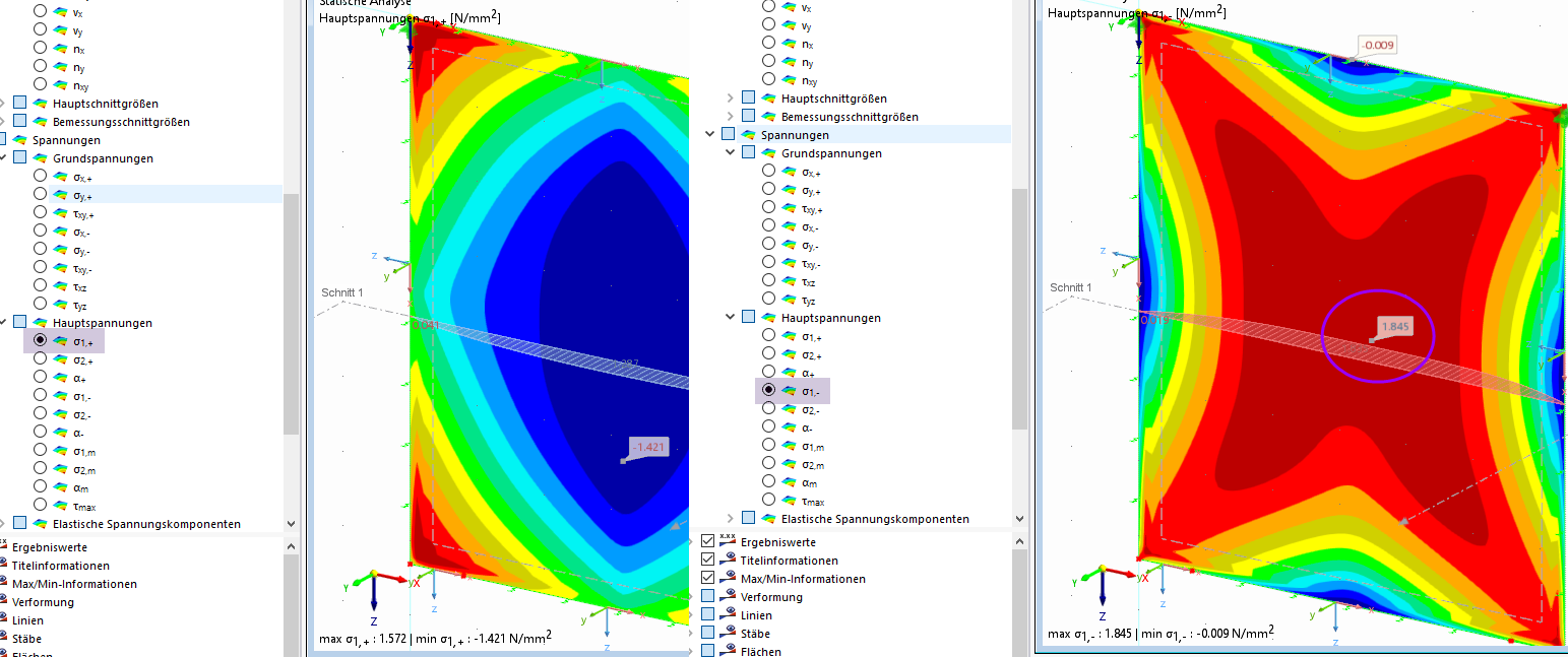
This becomes apparent when looking at the stress evaluation.
The maximum stress also occurs at the edge of the pane.
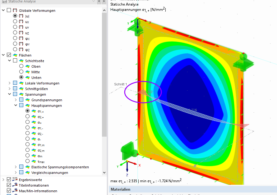
If you now arrange line hinges (release phi_x) at the edges of the side surfaces, you will get the expected stress pattern with the maximum stress in the middle of the field.
In my first video, I did not go into this topic in detail because I wanted to show a basic modeling procedure. However, for your case, I would recommend adding these hinges.
Best regards
Ulrich Lex
Hello Mr. Lex,
thank you very much for your help; with the line hinges I am achieving very good results.
However, I have now also tried the "Glass Design" addon. The results, however, differ significantly from the reference values. The stress distribution also differs significantly from the other RFEM 6 model. The following boundary conditions apply:
FE mesh 2 cm
Geometry 1.5 x 1.5 m
| Construction |
Float glass |
12 mm |
|
Spacer |
14 mm |
|
Float glass |
12 mm |
| Summer |
Pressure |
103 kN/m² |
|
Altitude |
600 m |
|
Meteorological |
2 kN/m² |
|
Temperature difference |
+20 °C |
| Winter |
Pressure |
99 kN/m² |
|
Altitude |
-300 m |
|
Meteorological |
-4 kN/m² |
|
Temperature difference |
-25 °C |
Only the climate loads mentioned above were applied as loads. The combination factors of the standard were not considered. The following stresses result:
RFEM 6 surface model with line hinges
|
|
Stresses [N/mm²] |
Deviation |
| Summer |
top |
5.90 |
101.55 % |
|
bottom |
4.22 |
78.29 % |
| Winter |
top |
3.80 |
76.77 % |
|
bottom |
5.29 |
99.58 % |
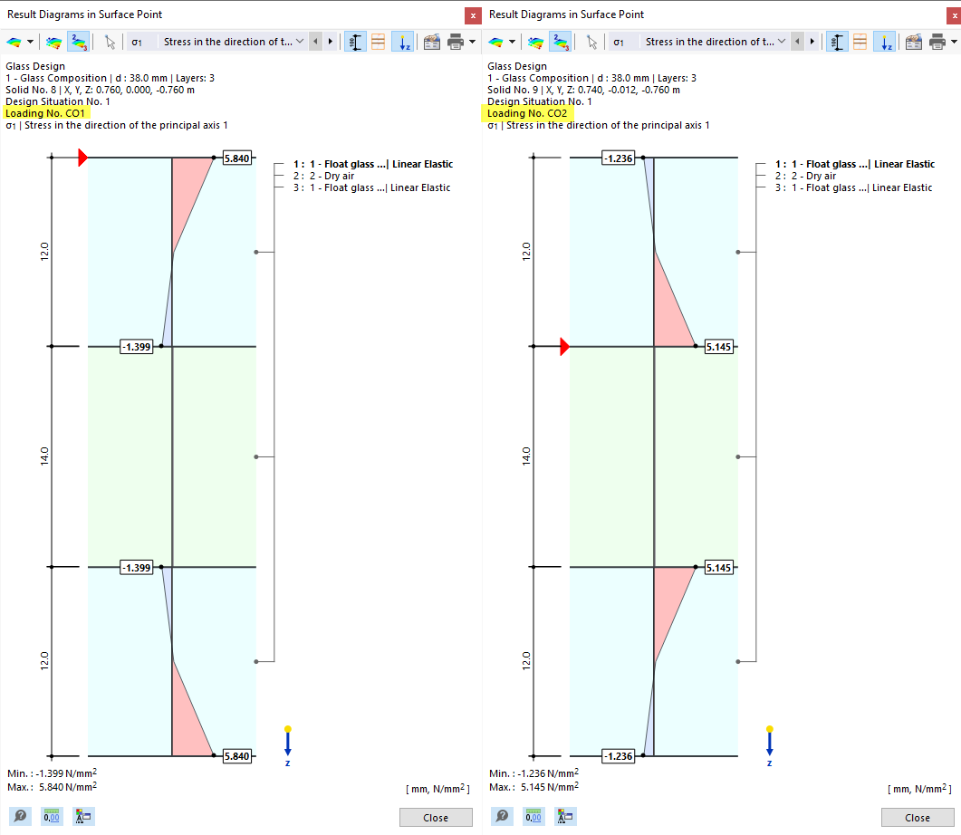
RFEM 6 Glass Design
|
|
Stresses [N/mm²] |
Deviation |
| Summer |
top |
4.89 |
84.22 % |
|
bottom |
1.33 |
24.66 % |
| Winter |
top |
1.16 |
23.47 % |
|
bottom |
4.27 |
80.06 % |
Reference calculation SJ Mepla 6
|
|
Stresses [N/mm²] |
| Summer |
top |
5.81 |
|
bottom |
5.39 |
| Winter |
top |
4.95 |
|
bottom |
5.33 |
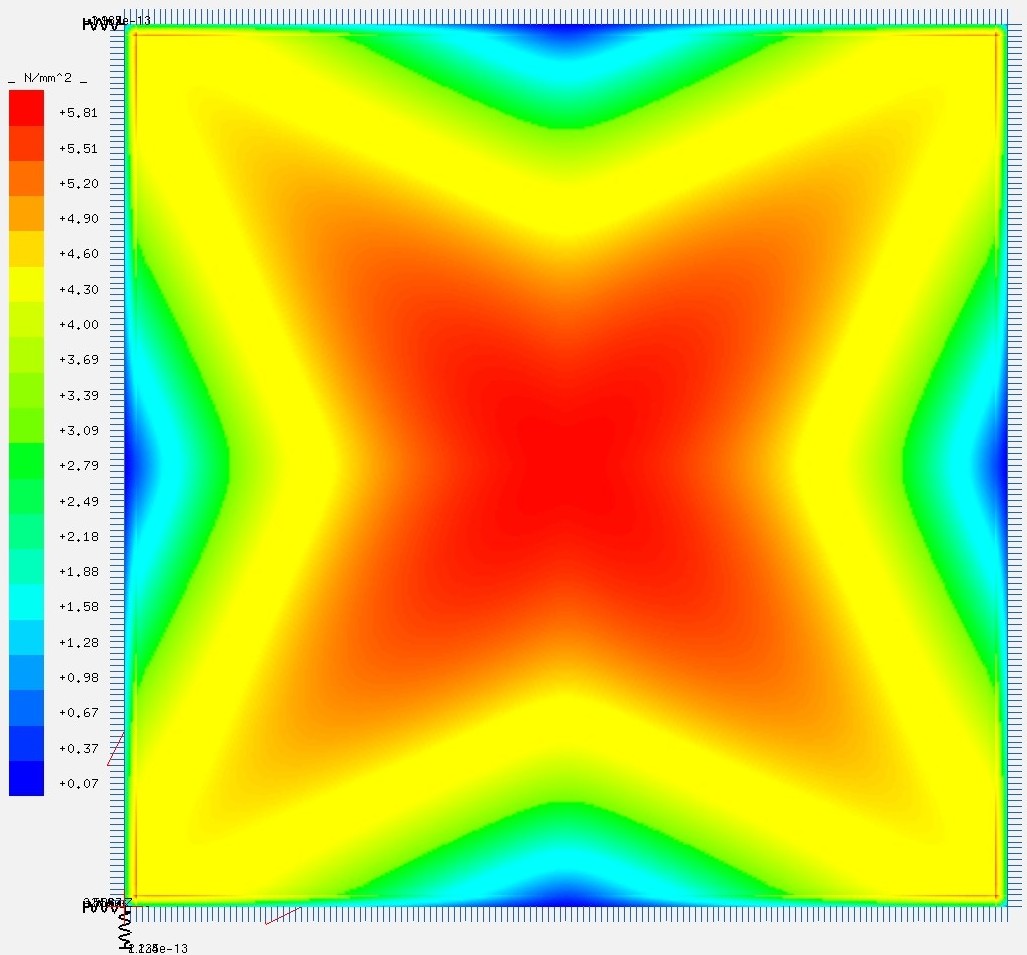
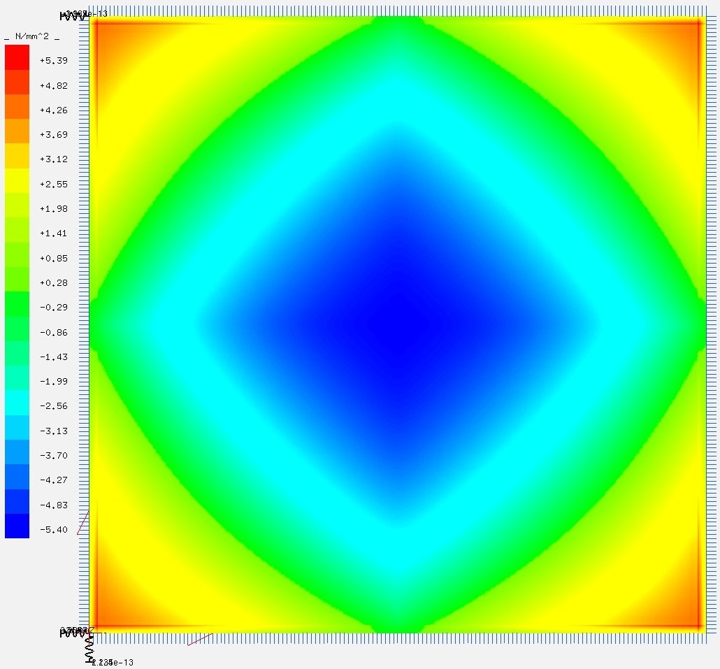
The following stress distributions result for the load case summer according to SJ Mepla 6:
Top side
Bottom side
I think the higher stresses on the two mostly compression-loaded sides in SJ Mepla are due to the spacer. In the calculation, the spacer was specified with a width of 5 mm and a modulus of elasticity of 100 N/mm².
Why do the stresses in the "Glass Design" addon deviate so much from the reference model? I oriented myself on your webinar for the modeling. It would be very helpful if you could check my model for errors.
Glass Design 12mm Test.rf6 (1.0 MB)
Thank you very much for your help!
Immanuel Cordes
1 Like
Hello @Immanuel.Cordes,
Comparisons are always difficult for me to analyze because I do not have all the files and also do not have the reference calculation. What is important here, in my opinion, is also clear that the boundary conditions of all models are the same.
In your file, I have not noticed anything unusual at first glance. However, if I increase the spring stiffness of the bearings slightly, this also affects the maximum stresses. For example, for Cu, Y=8000 kN/m² at mid-span, I obtain these values
Perhaps you can compare your files in this regard.
Best regards
Ulrich Lex
1 Like
Hello Mr. Lex,
thank you very much for the explanations. That has helped me.
Best regards
Immanuel Cordes
1 Like