Hello,
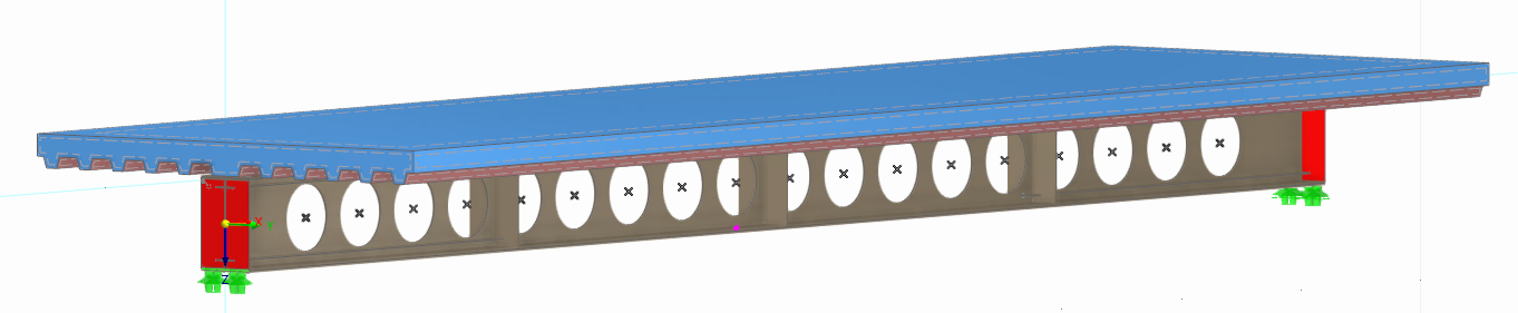
I am currently continuing the development of a nonlinear FE model of a composite steel–concrete perforated beam in RFEM 6 as part of my master’s thesis.
01_OKR_1_3.rf6 (2,7 MB)
I previously created a related topic concerning the concrete Damage model and its deactivation for linear buckling analysis:
The current question concerns the subsequent nonlinear incremental stability analysis of the same model.
- Steel perforated beam: S355, surface elements, nonlinear isotropic plastic material model.
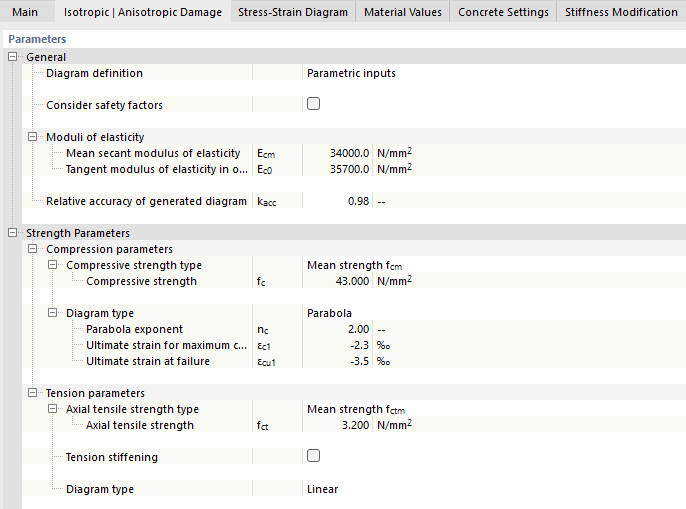
- Concrete slab: C35/45, solid elements, nonlinear anisotropic Damage model.
- Profiled steel sheeting: S350GD, surface elements, modeled explicitly.
- Shear connectors: discrete connectors with a nonlinear load–slip (Q–s) relationship.
- Plate bending theory: Mindlin (surface elements).

The main objective of the analysis is to investigate the behavior and failure mechanisms of the steel perforated beam, especially web-post buckling, local plasticity and the possible development of a plastic mechanism in the bottom flange.
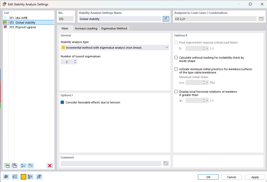
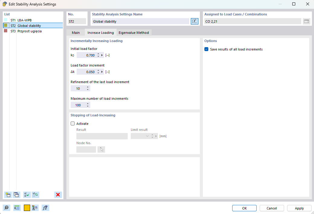

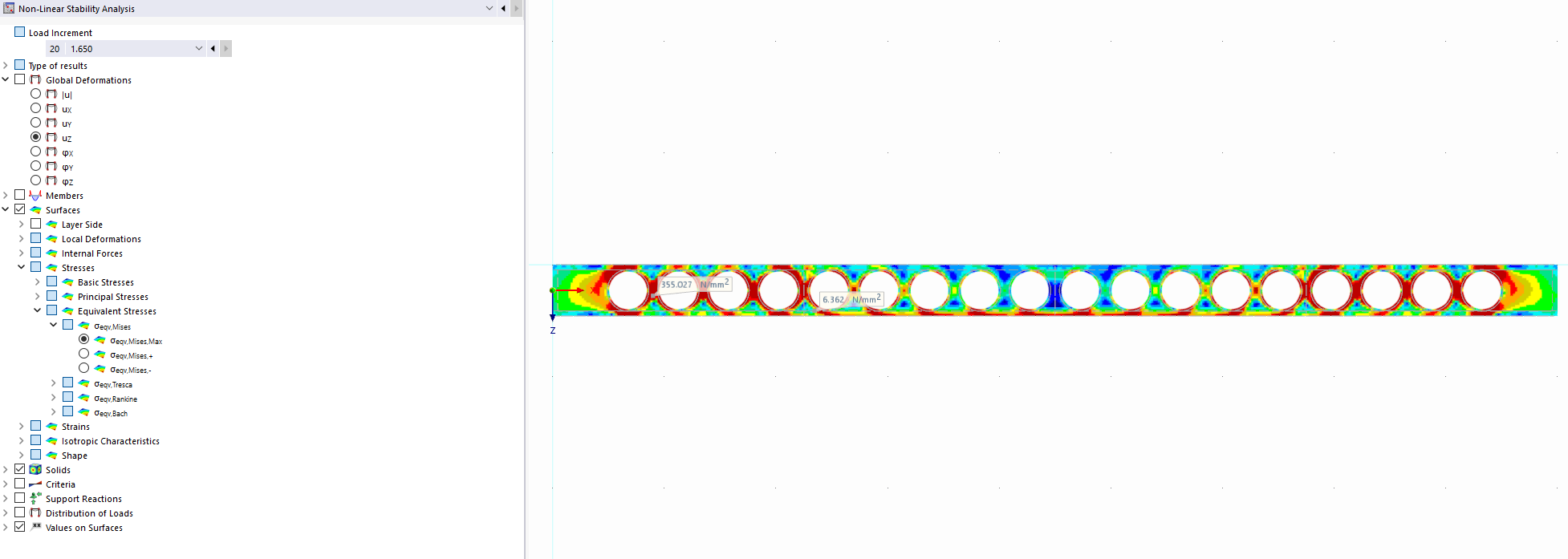
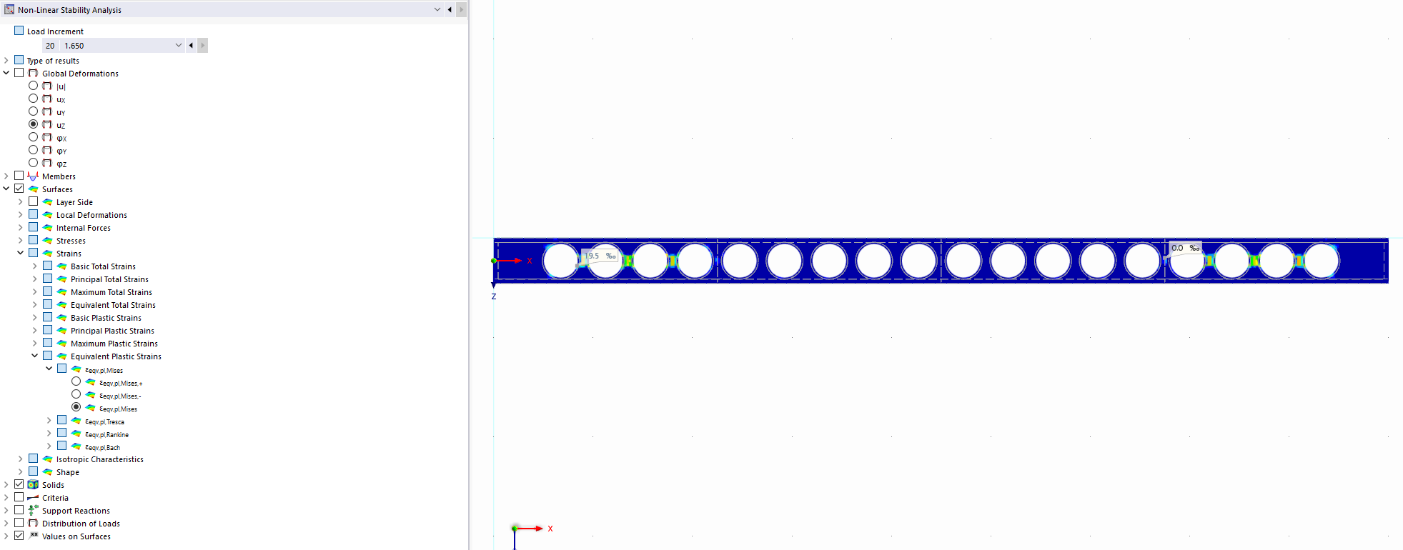
During the nonlinear incremental stability analysis, the calculation currently stops at a load factor of approximately 1.65. At this stage, plastic strains occur mainly locally in the web post, particularly in the region affected by web-post buckling. However, the bottom flange is still almost entirely elastic.
In an earlier model with linear-elastic concrete, the analysis could continue to significantly higher load levels. Yielding of the bottom flange started at approximately a load factor of 1.8.
I have already tested different nonlinear solution approaches, including the post-critical Newton-Raphson method, but the calculation still stops at approximately the same load level. The calculation stops before the maximum number of iterations is reached.
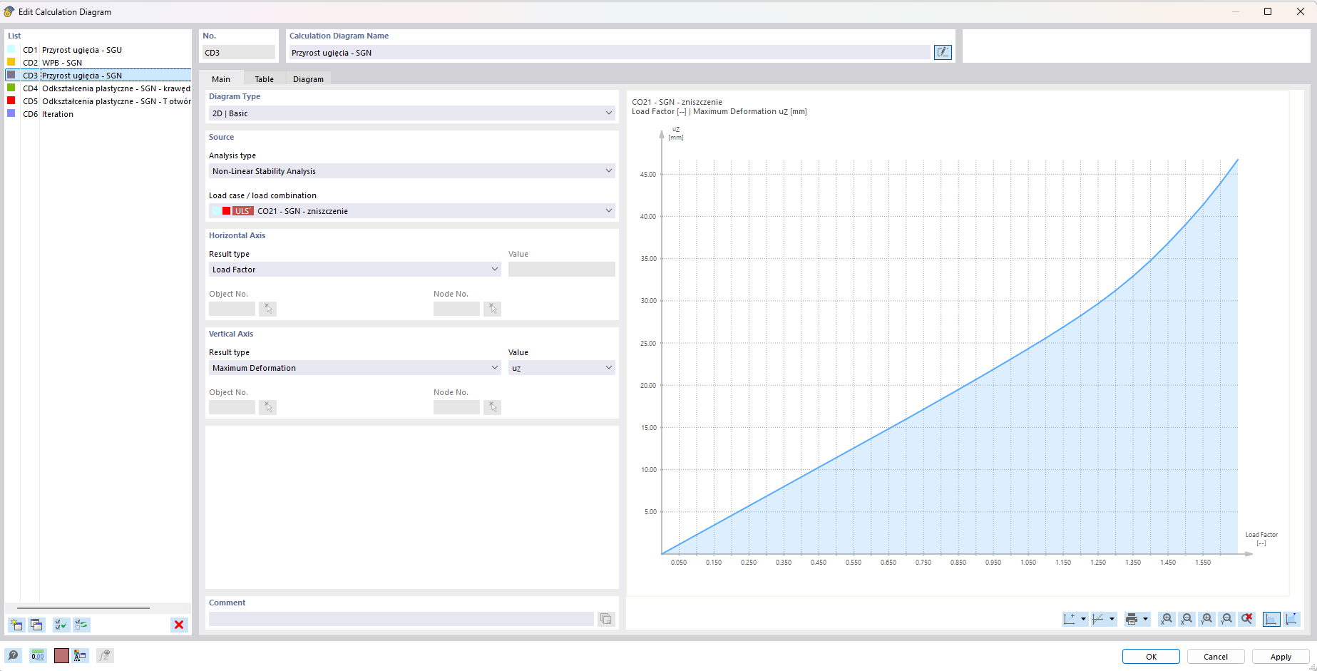
Therefore, I would like to ask:
-
Does RFEM have any internal limitation related to the magnitude, distribution or extent of plastic strains that can terminate a nonlinear incremental stability analysis? Can relatively localized plasticity and web-post buckling reduce the global stiffness of the system sufficiently to prevent RFEM from finding a further equilibrium solution, even if the bottom flange remains almost entirely elastic?
All user-defined stopping criteria for deformation and plastic strain have been disabled, so the analysis is not being terminated by these limits. -
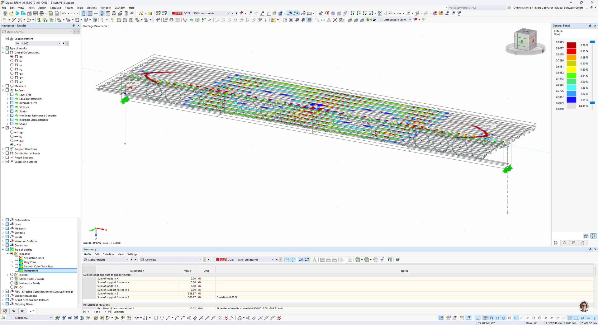
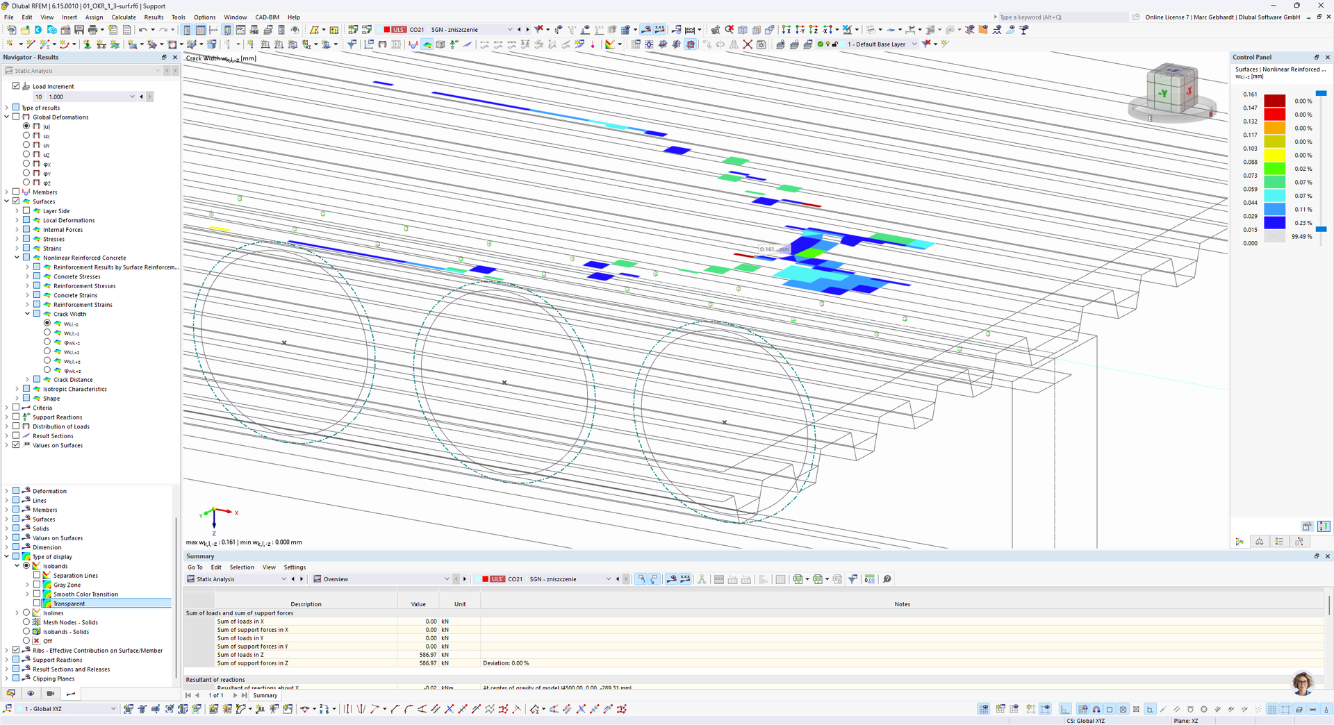
In the nonlinear concrete model, I observe very high local compressive stresses in some solid elements, especially close to the shear connectors and load-transfer regions. Could this local behavior and the associated stiffness degradation of the concrete be responsible for the calculation stopping before significant yielding develops in the steel bottom flange?
The profiled steel sheeting is modeled explicitly and acts as the lower reinforcement of the composite slab, while conventional reinforcement is mainly located in the upper part of the slab, but I currently do not model the reinforcement mesh explicitly because the main subject of the study is the steel beam, rather than the detailed behavior of the reinforced concrete slab.
Would the use of a Quast or Modified Quast tension-stiffening model be a reasonable simplified way of accounting for the influence of the upper reinforcement mesh without explicitly modeling the reinforcing bars?
I understand that tension stiffening does not physically replace the reinforcement itself, but I am wondering whether it could provide a sufficiently realistic approximation of the slab stiffness and cracking behavior for a model whose primary purpose is the analysis of the steel perforated beam.
I would be very grateful for any comments regarding the numerical behavior of the model, the interpretation of the nonlinear stability limit, and the simplified modeling of slab reinforcement.

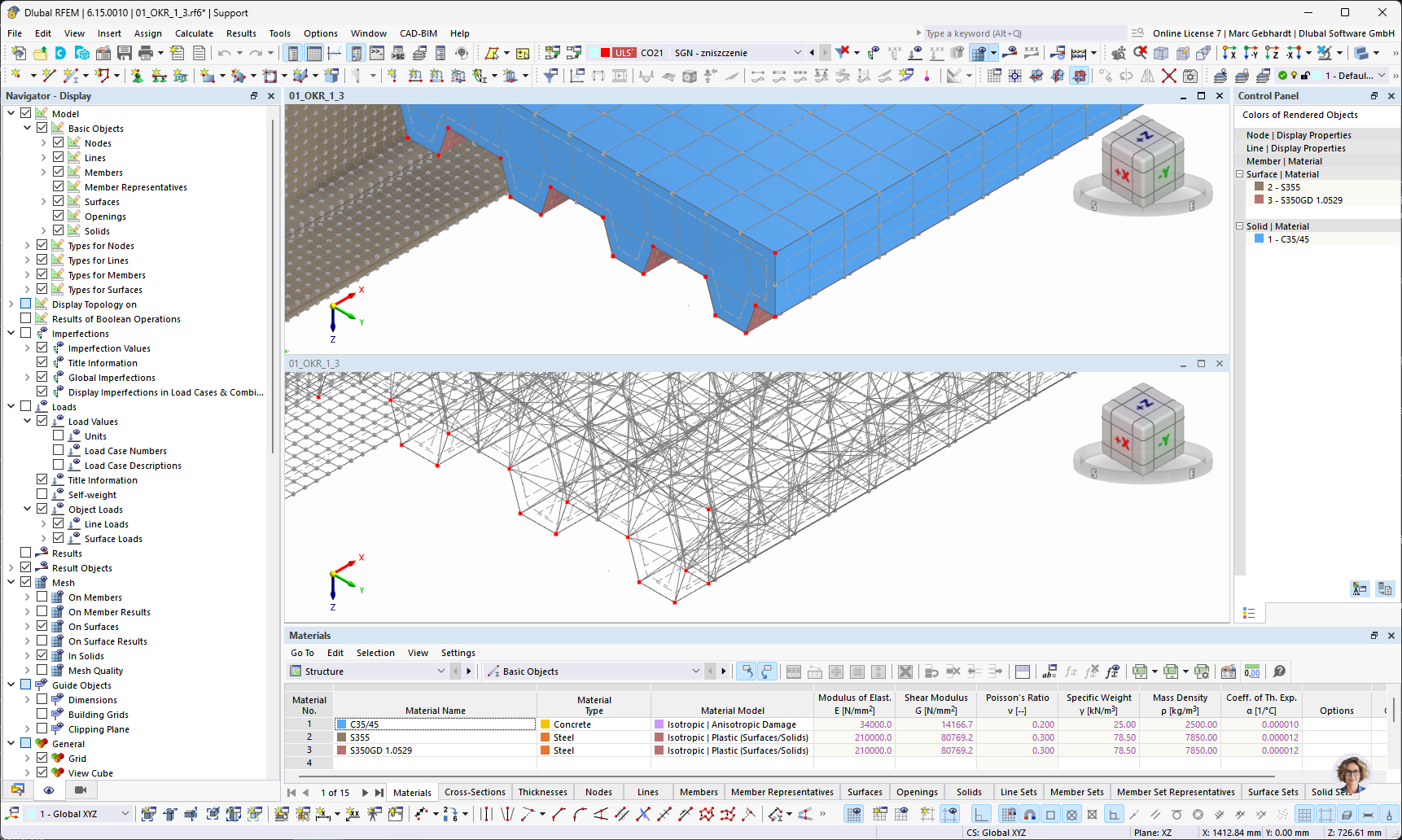
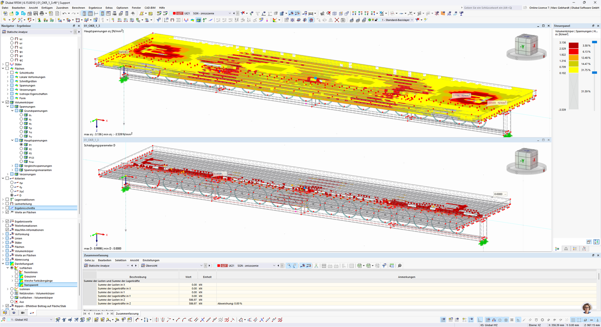
 Here, the calculations are set up according to second-order theory (not large deformation) and the standard Newton-Raphson method (instead of post-critical). In my opinion, this should also be investigated further. I’d also like to offer you one more piece of advice: You’ve set the convergence criteria much more leniently; I can only advise against this, especially to such a high degree. I’ve reset them to the default values. Please also take a look at this