Pile Design Workflow

Hi all,

I have recently started learning the tool in order to do a bachelors thesis. Initially all went well. I followed the 20 part steel frame tutorial without any issues. However, I couldn't find many tutorials on geotechnical design. I followed the webinar on pile design (dlubal pile design webinar - Search Videos), however, I consistently recieve the 1327 error. It occurs during the calculation phase for the 3 load conditions (those being soil self weight, pile self weight and for the applied load). I have followed the steps precisely but I cannot find what my flaw is. I understand that the webinar is a bit outdated, but unfortunately I was not able to find a replacement.

I have attached the model to this post:
Single Pile from webinar.rf6 (1.9 MB)
I would greatly appreciate your help and potential feedback!

Hi Oskar,

Thank you very much for your request! :blush:

Regarding the issue you described: The error is caused by instabilities in the model. This can occur, for example, due to a missing linearization (nil phase) of the soil.

A separate calculation of the basic load cases is not required for the analysis in this case. Please refer to the following FAQ for more details: https://www.dlubal.com/en/support-and-learning/support/faq/005357

:backhand_index_pointing_right: Additional Context

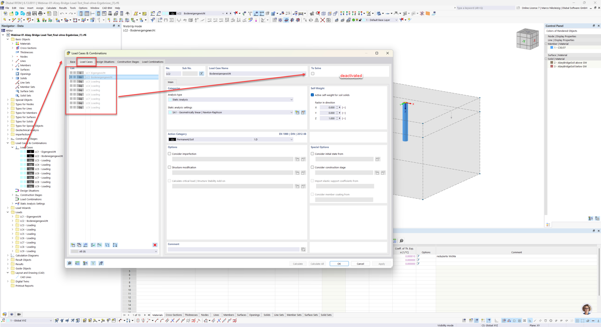
In the webinar model, the load cases were actually set to inactive, although this was not explicitly shown during the session. The following screenshot illustrates this setting clearly.

:backhand_index_pointing_right: Further Resources

Regarding your question about additional webinars on bored piles: Currently, the webinar you mentioned is the only one available on this topic. However, I recommend the following Knowledge Base article on pile modeling: https://www.dlubal.com/en/support-and-learning/support/knowledge-base/001955. The modeling approach described there allows for faster calculations of bored piles.

If you have any further questions or need assistance with your model, feel free to reach out – I'm happy to help!

Best regards
Marco Nikoleizig

1 Like

Hi Marco,

Thank you very much for your reply. I understand it well now and I managed to fix this specific issue. However, the results that are created from this model are still wrong in some way. Even when I increase the applied point load to a massive or very small value the results do not change and the stresses visible in both the soil and pile do not reflect this force. Previously I thought it can be attributed to this error but that's not the case anymore. I assume I have done another modelling error but I am not quite sure where.

Again thank you very much for your help!

Hi Oskar,

Without a more detailed description of the issue in your model, it’s a bit difficult to provide a precise solution. However, here’s a useful starting point: Check the FE mesh settings, especially for solid elements.

In your model, the target FE mesh size is set to L_FE = 2 m, while in the webinar model it is only 0.65 m. This difference can significantly affect the results and may be the source of the problem.

You can find more details in the online manual: https://www.dlubal.com/en/downloads-and-information/documents/online-manuals/rfem-6/000242

Additional tip:

It may also help to download the webinar example model and compare it directly with your own model. This often makes it easier to spot differences: https://www.dlubal.com/en/downloads-and-information/examples-and-tutorials/models-to-download/005465

If you can share more details about the issue or upload your model, feel free to do so – I'd be happy to take a closer look :+1:

Best regards
Marco Nikoleizig

1 Like

Hi Marco,

I believe the issue arises because for some reason the load isn't applied at all. I can set the point load to 1kN or 1000kN and it makes no difference on the results. The program doesn't even need to recalculate anything. I have now found the reason for this. Within the construction stages I had the LC3 (nodal load) set as a non permanent load:


Having fixed that the load was now properly represented and calculated in the model. Can you perhaps explain why the load, when set as non-permanent, wasn't being considered at all in the calculation?

However, I noticed another interesting thing. When the nodal load was set relatively low (e.g. 1000 kN) the calculation ran fine. Within the calculation window the displacement vs iteration graph was linear. However, when I set the load to the value from the webinar (3500 kN) the first dozen iterations displacement was linear, but then displacements shot up very quickly and then the calculation stopped with error 10134 "The stiffness matrix is singular | The structure is unstable | FE mesh node No. 13, in direction Z, increment 18".
I am not quite sure how to interpret this. It may be simply the failure of the pile, however, this is the same value that the webinar used. If it is simply the failure, how can I better observe it? Rather than the calculation simply crashing due to instability.

At 3000 kN the calculation still completes. I wanted to recreate the maximum deformation- member internal forces diagram, however it seems oddly linear and not similar to the webinars example. I will attach them in the next comment I am being limited on media uploads.

As you requested here is also the model:
Single Pile from webinar 2.rf6 (2.0 MB)

Thank you very much for your help again! You've been extremely helpfull.


Webinars diagram

my diagram

While plausibly similar, my diagram seems to miss the detail of the webinar's diagram.

Hi Oskar,

thanks for your question.

:backhand_index_pointing_right: Why wasn’t the non-permanent load considered?

You can find the explanation in the online manual for the Construction Stages Analysis add-on: https://www.dlubal.com/en/downloads-and-information/documents/online-manuals/rfem-6-construction-stages-analysis-for-rfem-6/000702

Please refer to the section "Permanent".

:backhand_index_pointing_right: In brief:

  • Loads defined as permanent are automatically considered throughout the construction stages.
  • Non-permanent loads must be explicitly assigned to the respective construction stages.
  • If they are not assigned, they will not be included in the calculation.

:backhand_index_pointing_right: Instability at a load intensity of 3500 kN

The load-bearing capacity of the pile depends on its surface resistance, which is defined in:

  • Pile Resistance → Skin Resistance
  • Pile Resistance → Base Resistance

This means the total resistance depends on:

  • the pile length, and
  • the pile diameter

Comparison:

  • Your model → Cross Section No. 1: D = 1270 mm
  • Webinar model → D = 1300 mm

Even a small difference in diameter can significantly influence the pile resistance.

:backhand_index_pointing_right: Further documentation

For more details, see the Geotechnical Analysis add-on manual: https://www.dlubal.com/en/downloads-and-information/documents/online-manuals/rfem-6-geotechnical-analysis/005955

:backhand_index_pointing_right: Reason for the instability message

If the applied load exceeds the pile resistance, the pile fails due to plastic yield in the surrounding soil. This results in the instability warning you observed.

If you have any further questions or want to review your model together, feel free to reach out.

Best regards
Marco Nikoleizig

1 Like