I need to model and study the following reinforced concrete geometry. I cannot find any information on this particular case concerning reinforced concrete ribs in the online help.
Could you please indicate a modeling approach that would allow for compliant reinforced concrete checks?
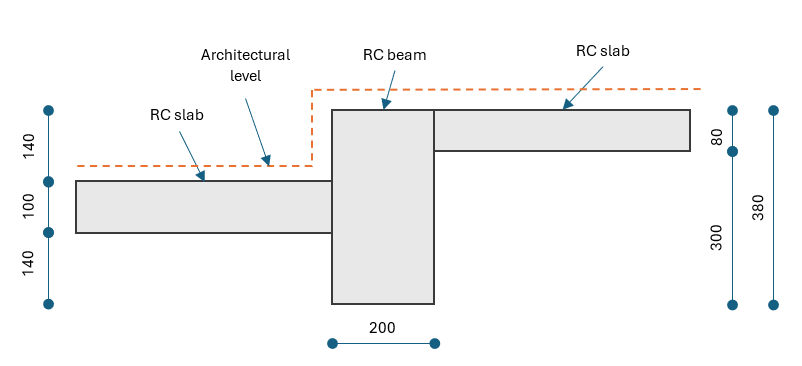
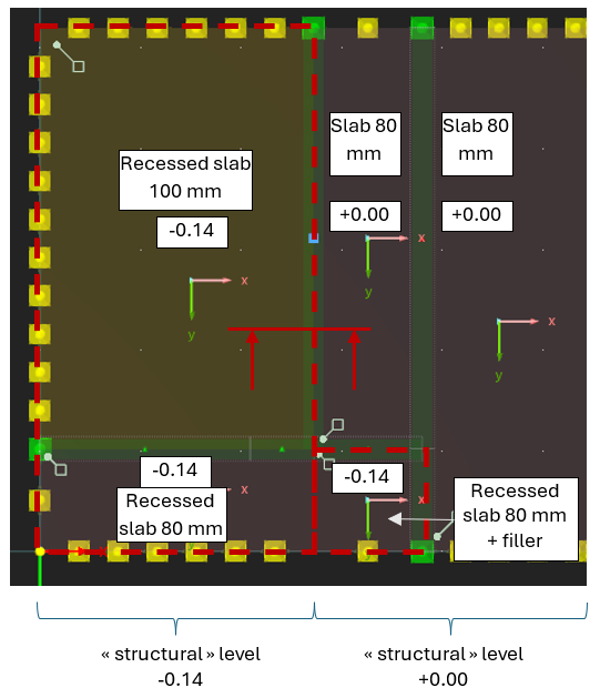
The section above is shown in red in the plan view below. The raw structural levels are a bit complicated, and the slab thicknesses vary. The load to maintain the +0.00 level on a lower slab is not a problem for me (a permanent load will suffice), but I cannot find how to model the structure offsets so that the reinforcements are correctly detected and verified, as well as the reinforced concrete sections.
The beam forming the opening frame is lower than the two beams that appear "vertically" in the plan view below. I am curious to know how to properly model this offset.
The Member type Rib can only be used with surfaces lying in the same plane. Therefore, a different approach is needed.
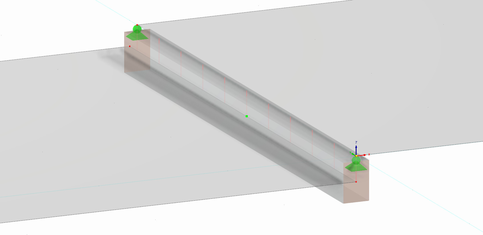
If you want to analyse the shown detail as a member, I recommend the following procedure:
Model the two slabs and the member in its original position.
The lower slab and the member can be connected directly as they lie in the same plane.
Connect the lower slab/member with the upper slab using a Rigid Link (line-line-connection type).
Create the combined cross-section of the rib with the desired reinforcement layout in RSECTION.
Assign a member of type result member with the created cross-section of step 4 to the line of the upper slab.
Design the result member with the Concrete Design add-on.
The use of RSECTION is necessary because there's currently no equivalent cross-section in the library that is compatible with the concrete design add-on.
If you don't want to use RSECTION, you won't be able to consider the lower slab in the rib design but only the upper one. If you want to use this approach, assign a rib member to the line of the upper slab and connect the lower slab to the upper slab using a rigid link:
Thank you Clemens. I feared something of the sort, but as long as there is a workaround, it's acceptable.
Two questions arise:
Isn't the section type TUOF or TU2OF compatible with the concrete design add-on?
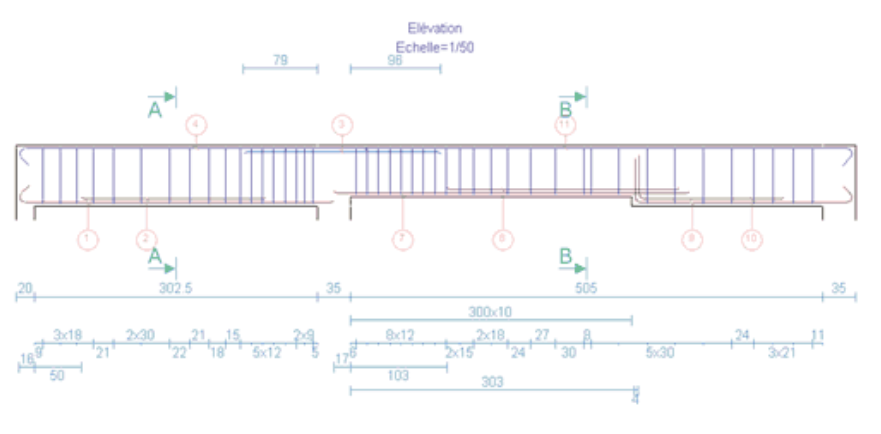
Is there a way to analyse a stepped section concrete rib? The beam that appears on the horizontal axis has a stepped section (the right side is 140 mm taller than the left side). If I chose a rib type, the concrete beam is discontinuous and I cannot have a proper analysis. Should I rather scrap the rib "additional" stiffness and go for a continuous beam, stepped sections and rigid links to stitch the slabs and loads back together?
Here, the top level is maintained but the beam has a different drop on its span. In some cases, it can be the opposite (to allow for a door threshold, for example).
Can such cases be modeled in RFEM, either as a beam or as a reinforced concrete rib?
@clemens.gutmann Sorry to bug you about this, but I'm not sure about how to model this kind of case using Dlubal.
I believe deflection analysis would require a member set to work, but using a member set also leads to loosing granularity over the rebar configuration.
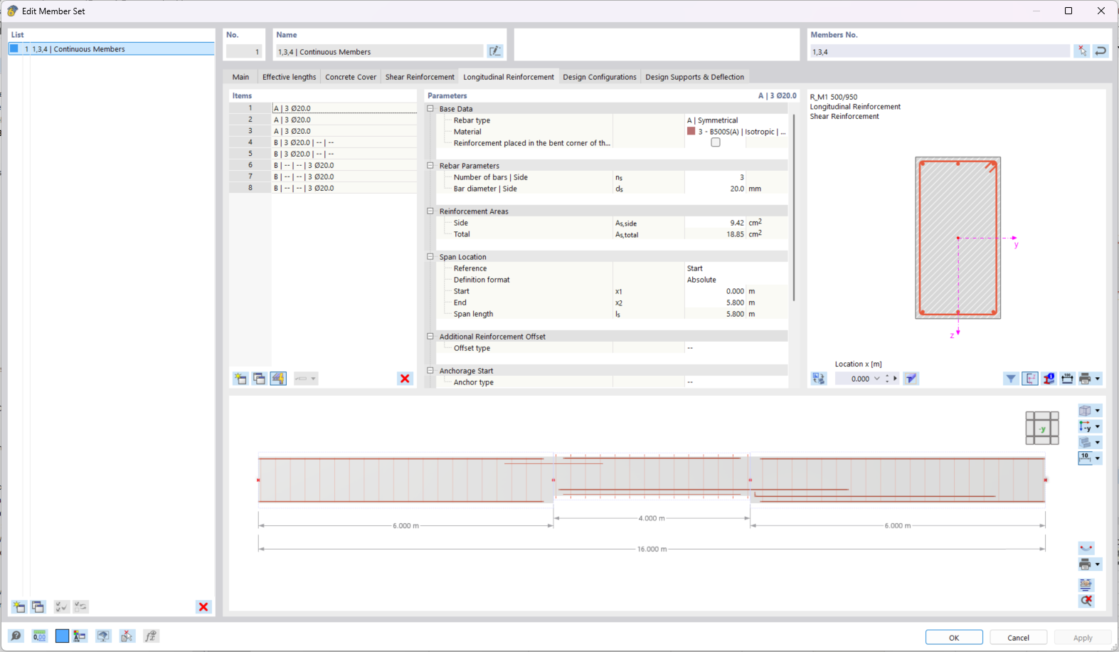
I would still recommend using a member set in this case. For the reinforcement design, you can define different longitudinal rebars and stirrups in different segments along the member set.
Also, we are currently working on improving and optimizing the reinforcement definition for member sets consisting of non-uniform (inconsistent) beams.