I have a question regarding your add-on "Push Over Analysis." Can it be applied to a building that is braced with reinforced concrete shear walls? On the internet, I have only found tutorials for steel frame structures/masonry shear walls. If a design with reinforced concrete shear walls is possible, I have the following question:
In the video for the add-on, nonlinear hinges were defined for the steel frame structure, i.e., a moment hinge as soon as the internal force M_(pl) is exceeded. Now, this is not so simple in reinforced concrete due to the cracks. Can such a hinge be calculated using a materially nonlinear design that depends on the reinforcement ratio and axial force?
Unfortunately, automatically creating the described hinge in RFEM 6 is not currently possible. However, if you manually determine the hinge backbone curve, you could define a hinge for modeling purposes in RFEM. That said, the interaction between axial force and moment capacity for hinges is not yet included in the program.
This interaction is widely discussed in literature as “P-M Interaction”. As you mentioned, it is particularly important for reinforced concrete due to cracking. One solution to handle these issues is the “fiber-section” model, where the nonlinearity is modeled in the cross-section materials rather than in the element itself.
For further context, I recommend checking Section 2 in the reference: “Nonlinear Structural Analysis for Seismic Design - A Guide for Practicing Engineers” (NEHRP Seismic Design Technical Brief No. 4).
In RFEM 6, we do have a model for walls that resembles the fiber model, and I will explain it below. While we haven’t reviewed this model for use in the Pushover Add-on, I encourage you to try it and see if the results meet your expectations.
Steps for testing the model:
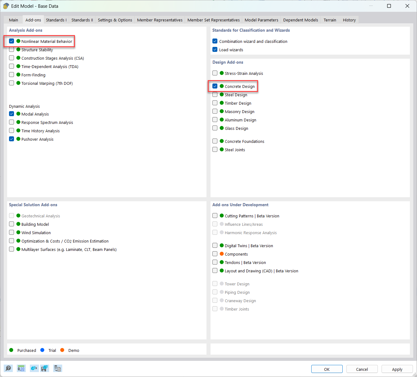
First, activate the Add-ons “Nonlinear Material Behaviour” and “Concrete Design”
Test this modeling in an isolated wall with 3-4 levels to better understand the behavior of this modelling option. In the best case scenario, you find a reference example that enables you to compare results. If you happen to develop this model, feel free to share it with me here, and I’ll be happy to assist you further!
Let me know how it goes, and don't hesitate to reach out if you have any more questions.
Hello Victor,
thank you very much for your contribution, it has already helped me a lot.
I have implemented your tips and used the material models you suggested.
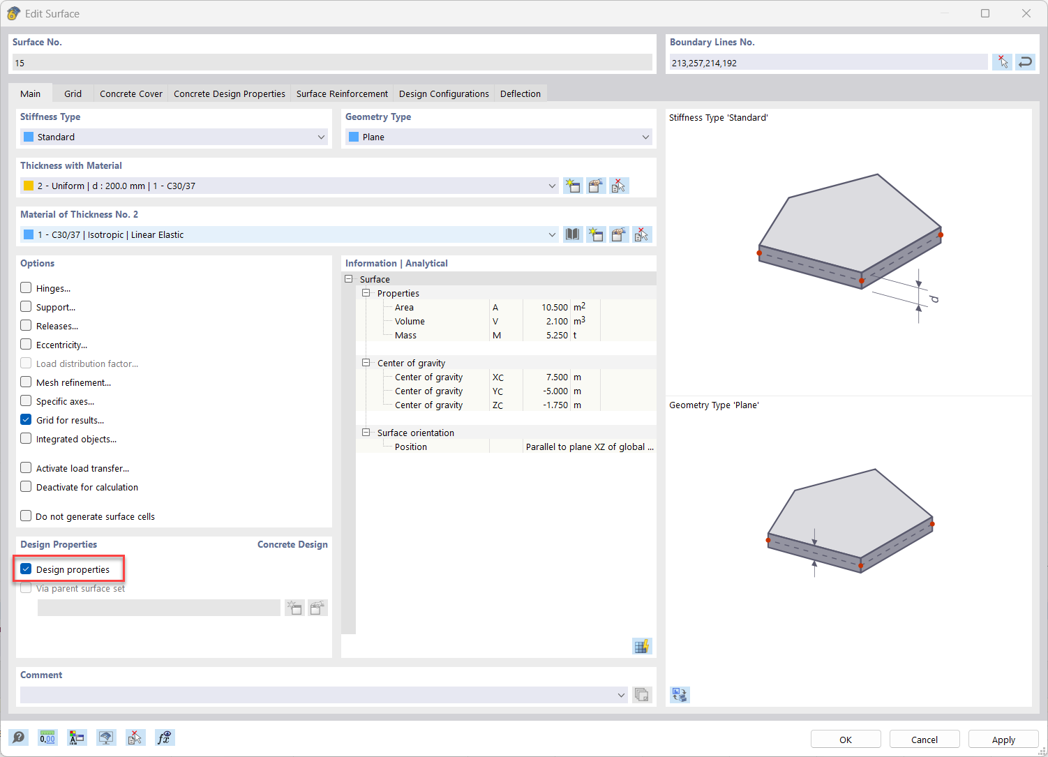
For my first attempt, I modeled a single wall panel to estimate the deformation in state II. Initially, I modeled the wall panel as a surface with thickness and entered the reinforcement as surface reinforcement. The normal force had an influence on the deformation.
However, I had the problem that the displacement or stiffness was independent of the reinforcement. Apparently, it was not considered for the stiffness.
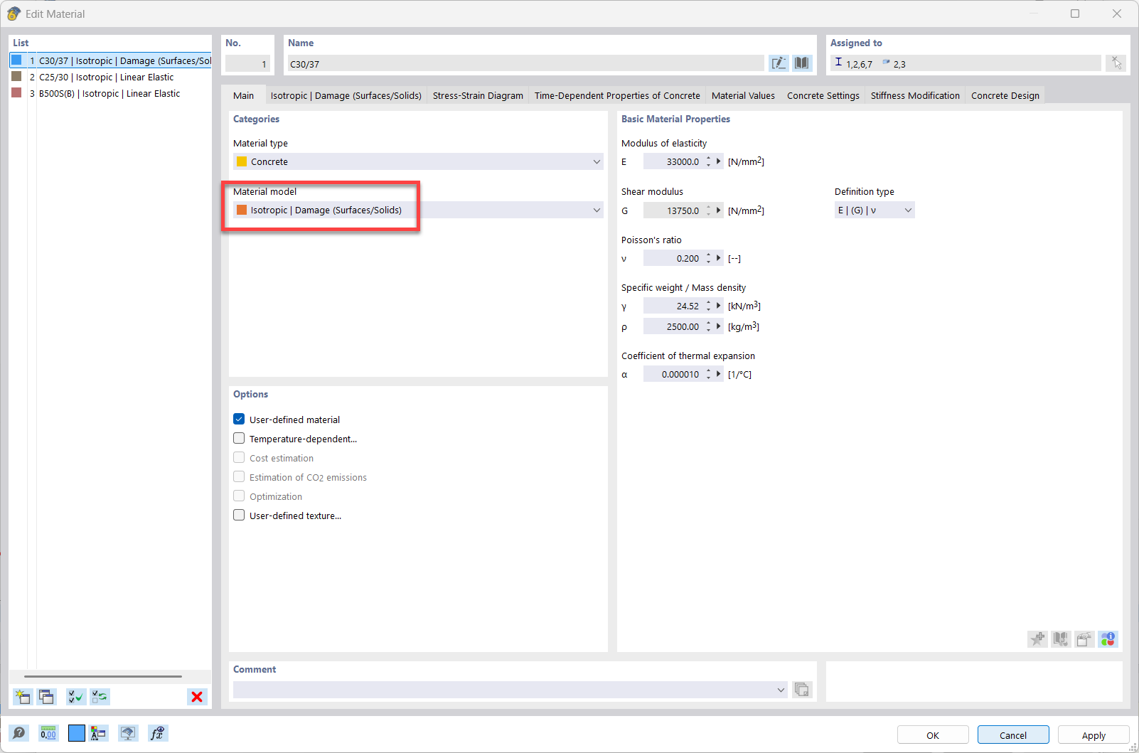
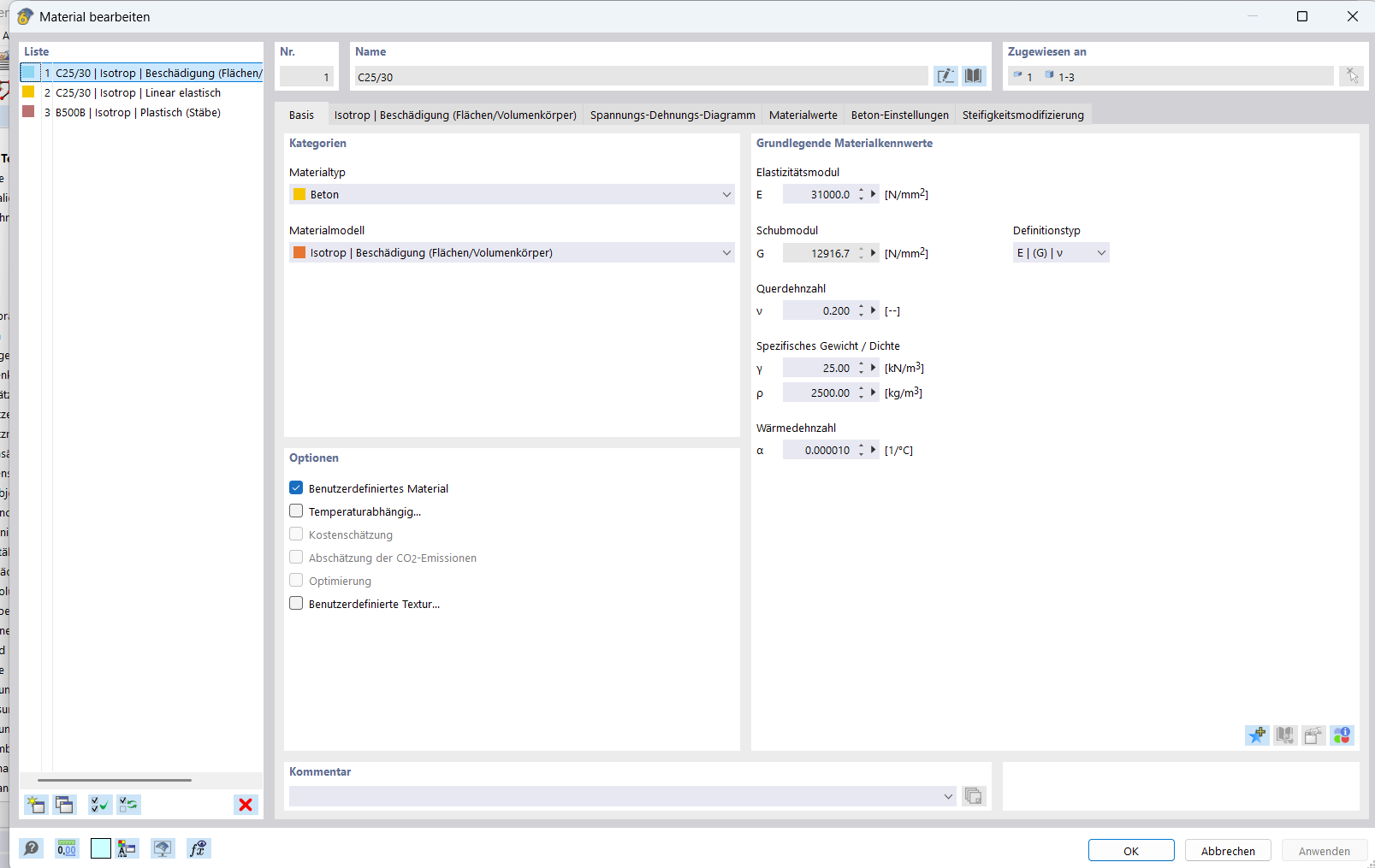
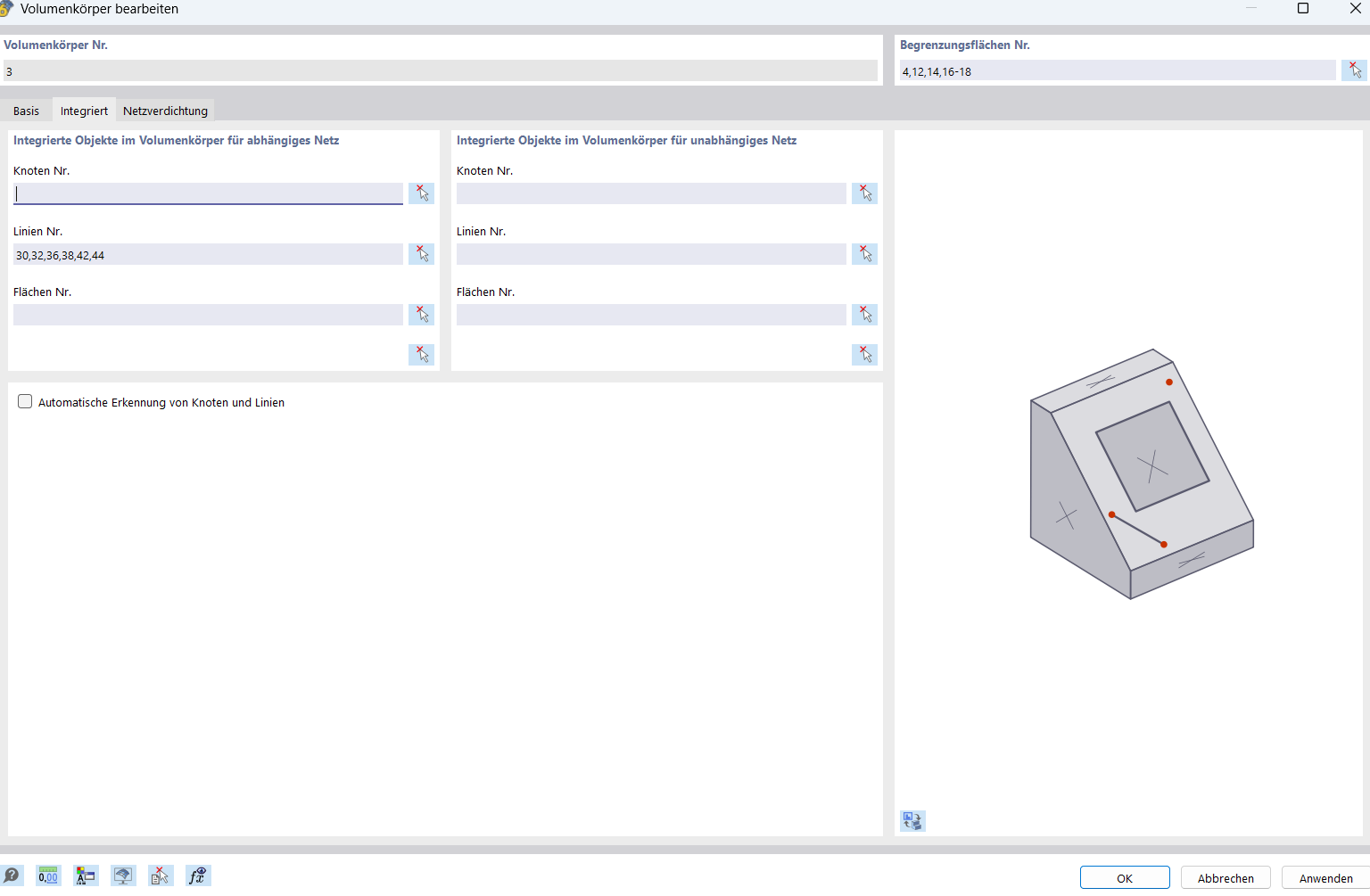
To improve my model, I then updated it from a surface model with thickness to a volume model. In my screenshots, you can see my model parameters for the concrete volume.
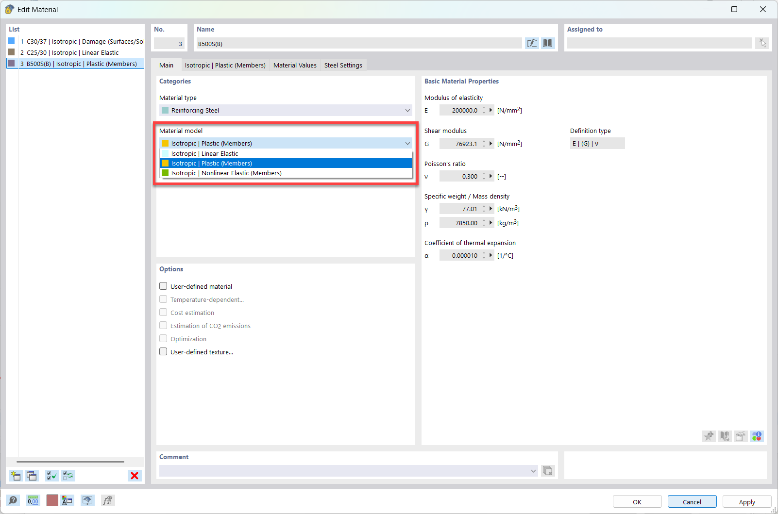
To consider the reinforcement, I also included it in the model with a plastic material behavior
After making these changes, the stiffness now also depends on the reinforcement: with more reinforcement, the deformation decreases. To check my model, I performed a manual calculation to determine the deformations at which force. Up to the range where the steel transitions into the plastic range, the deformation corresponds to my expectations. After the transition into the plastic range, I calculated significantly more deformation at significantly lower load. The model still has an extremely high residual stiffness after the transition into the plastic range, which seems unrealistic to me. What could be the reason for this? The reinforcement steel was already modeled with a bilinear stress-strain diagram.
Thank you for your reply and further insights on the modelling.
My first piece of advice is to continue working with the surface model, as the volume model increases the complexity of the problem without necessarily improving its accuracy. Both models serve as benchmark comparisons for each other, so sticking with the surface model for now might be a good idea.
Here’s what I found after reviewing your model:
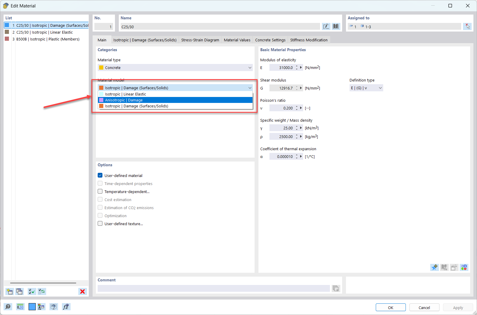
Concrete material change: After consulting with the colleagues who developed the nonlinear material for concrete, they recommended switching the concrete material to “Anisotropic”. This could potentially solve the issue you mentioned regarding the high residual stiffness after transitioning into the plastic range.
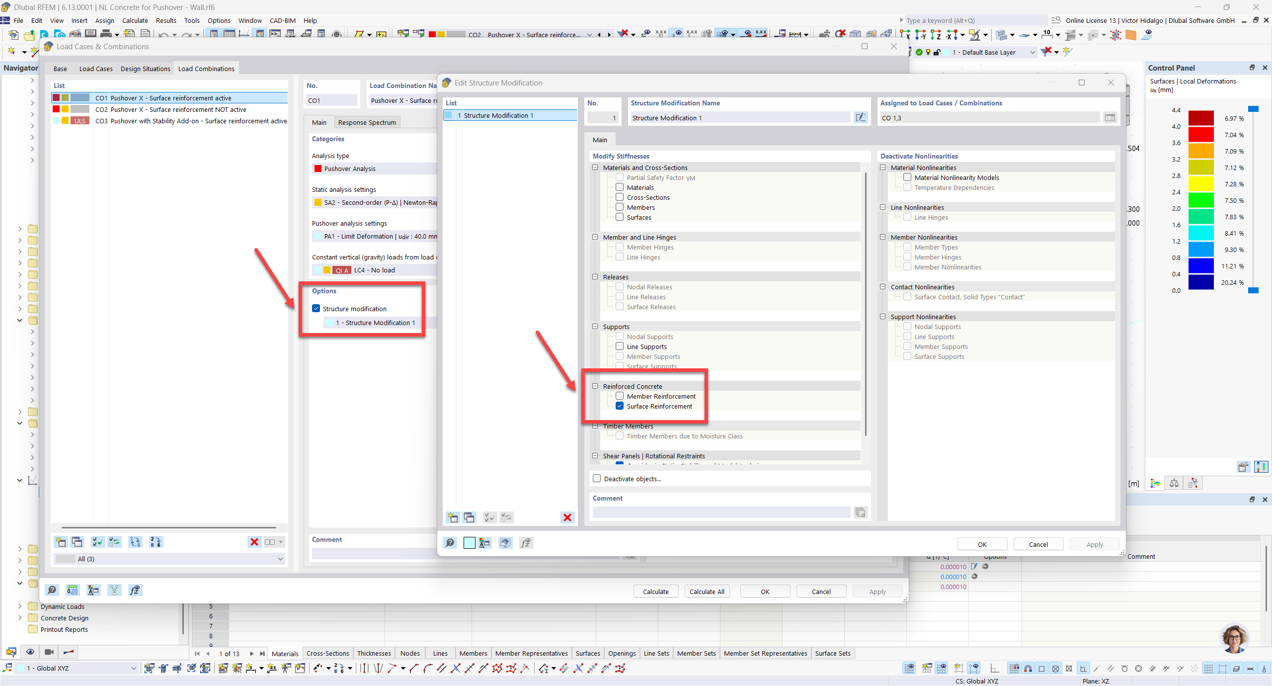
Wall model example: I’ve created a simple wall model for you, which you can find in the attached file. This model follows the guidelines I mentioned in my first message. After running a Pushover analysis with the corresponding Add-on, I found that this Add-on is currently ignoring the reinforcement on surfaces. I’ve reported the issue to the development team under BugID=576402
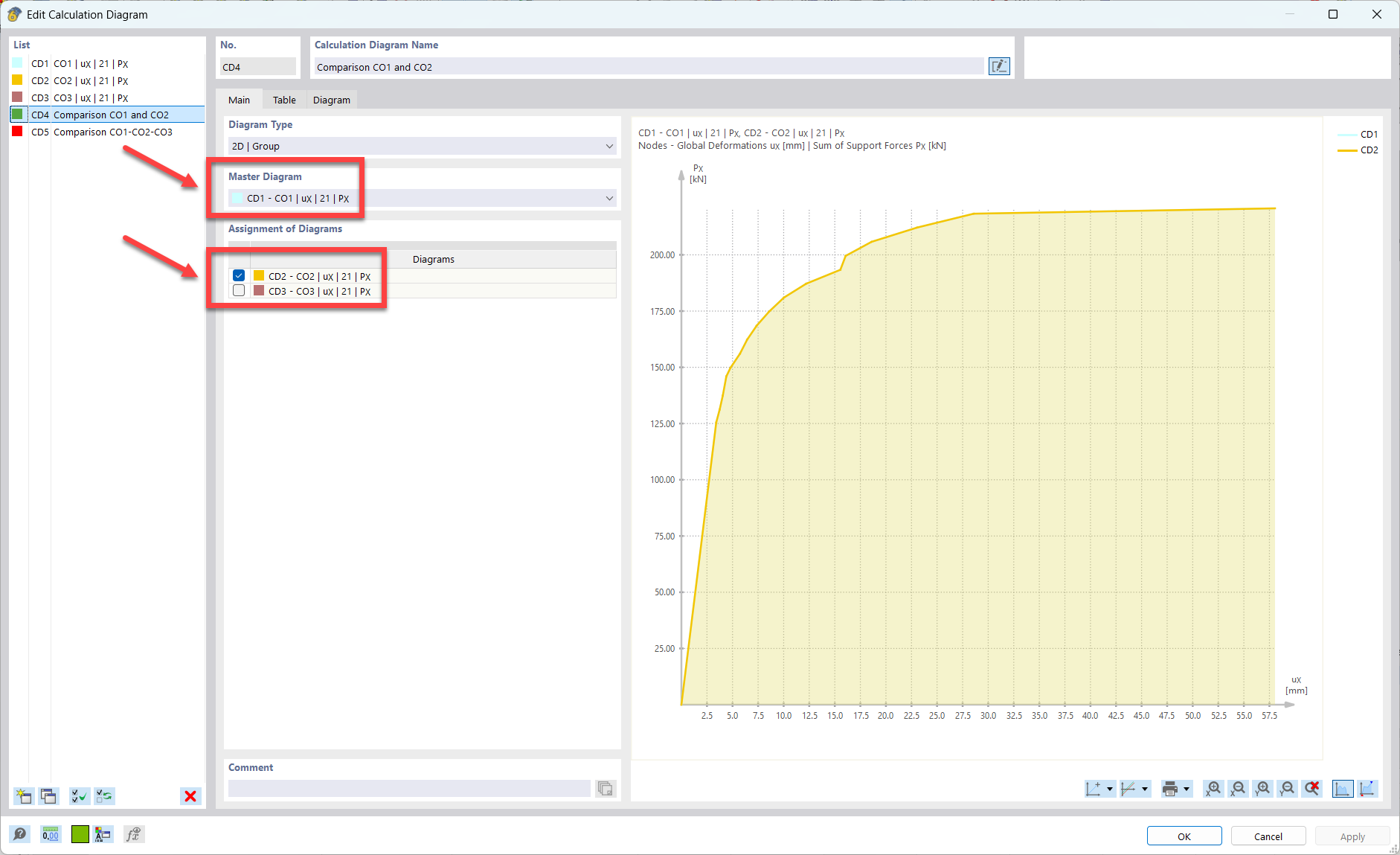
I created two Pushover analyses: one where the surface reinforcement is active (CO1) and one where it is not (CO2). The Pushover curves for both scenarios were identical. This means the reinforcement is not active in the CO1 analysis, and the curve reflects only the concrete action.
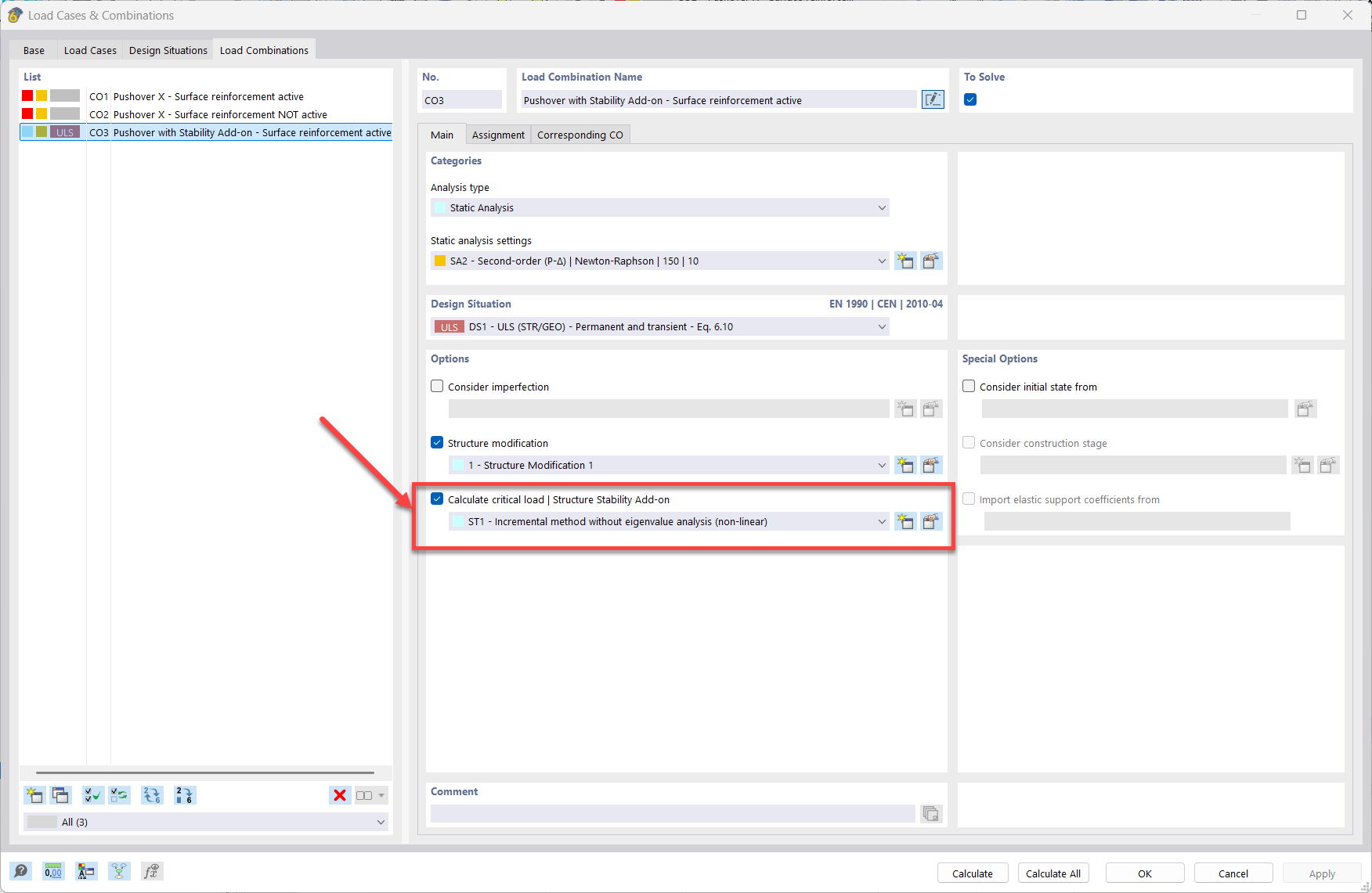
If you happen to have the “Structure Stability” Add-on, you can emulate the Pushover results. Please check the definition of CO3, particularly in the following options:
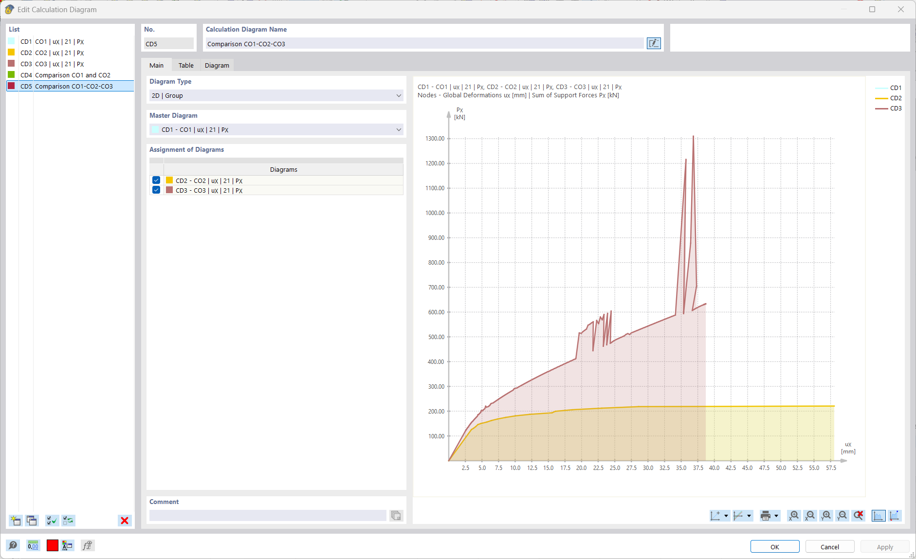
When comparing the Pushover curve from CO3 with CO1 and CO2, you can observe the impact of the reinforcement on the increased initial stiffness and higher maximum base shear force. However, you might notice some unexpected jumps in the graph. This happens because the stability analysis is not the same as a standard Pushover analysis, and it records several sub-steps.
Our development team is already working on BugID=576402, and I’ll get back to you with an update as soon as it is resolved.
Once again, thank you for your question and contribution to the community! We’ll certainly continue working on this topic, and I’m here to help if you have further questions.