Good day,
I have now managed to get my calculation running and would like to use the add-on Structural Stability to calculate the maximum permissible load for the system. I have watched the tutorial for this and have also made the settings accordingly. Now I have the problem that the calculation takes an extremely long time: it has been running for 18 hours and there is no end in sight. The CPU and memory should actually be sufficiently dimensioned and are only being used to a small extent.


What can I do or which settings can I adjust to speed up the incremental analysis process?
Flächenkontakt_0.01.rf6 (1.3 MB)
Thank you very much and best regards
Baustudi
Hello Baustudi,
I am currently trying to reproduce the problem on a tech computer. The calculation is still running.
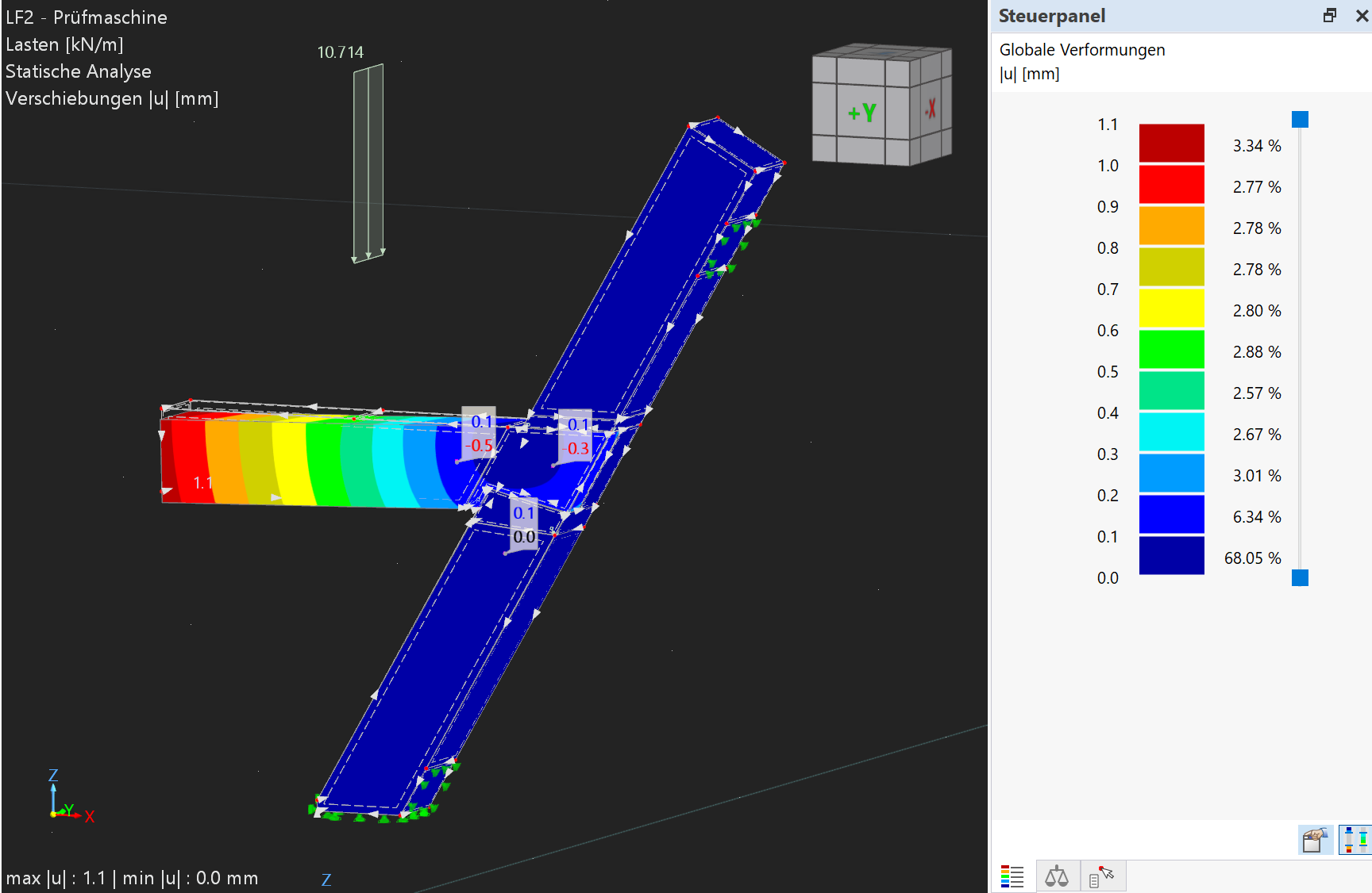
But one thing caught my attention. The deformation of load case 1 is over 1 m.
Is that really a realistic expected deformation?
If so, then it is no longer appropriate to calculate geometrically linear. It would then have to be calculated geometrically nonlinear with large rotations.
Best regards
Frank
So, now the cause seems to be clear. Load cases 1 and 2 did not converge. The model is apparently unstable. The load increase leads to ever larger deformations and does not find an end.
First, try to stabilize load case 1. In this FAQ you will find some helpful tips for this:
If the load case is stable, then test whether the static analysis of load combination 1 converges. If all that works, then you can proceed to the stability analysis of load combination 1.
Best regards
Frank
1 Like
Hello Frank,
thank you very much for your help! I will take a closer look at Load Case 1 again.
Best regards
Baustudi
Hello Frank,
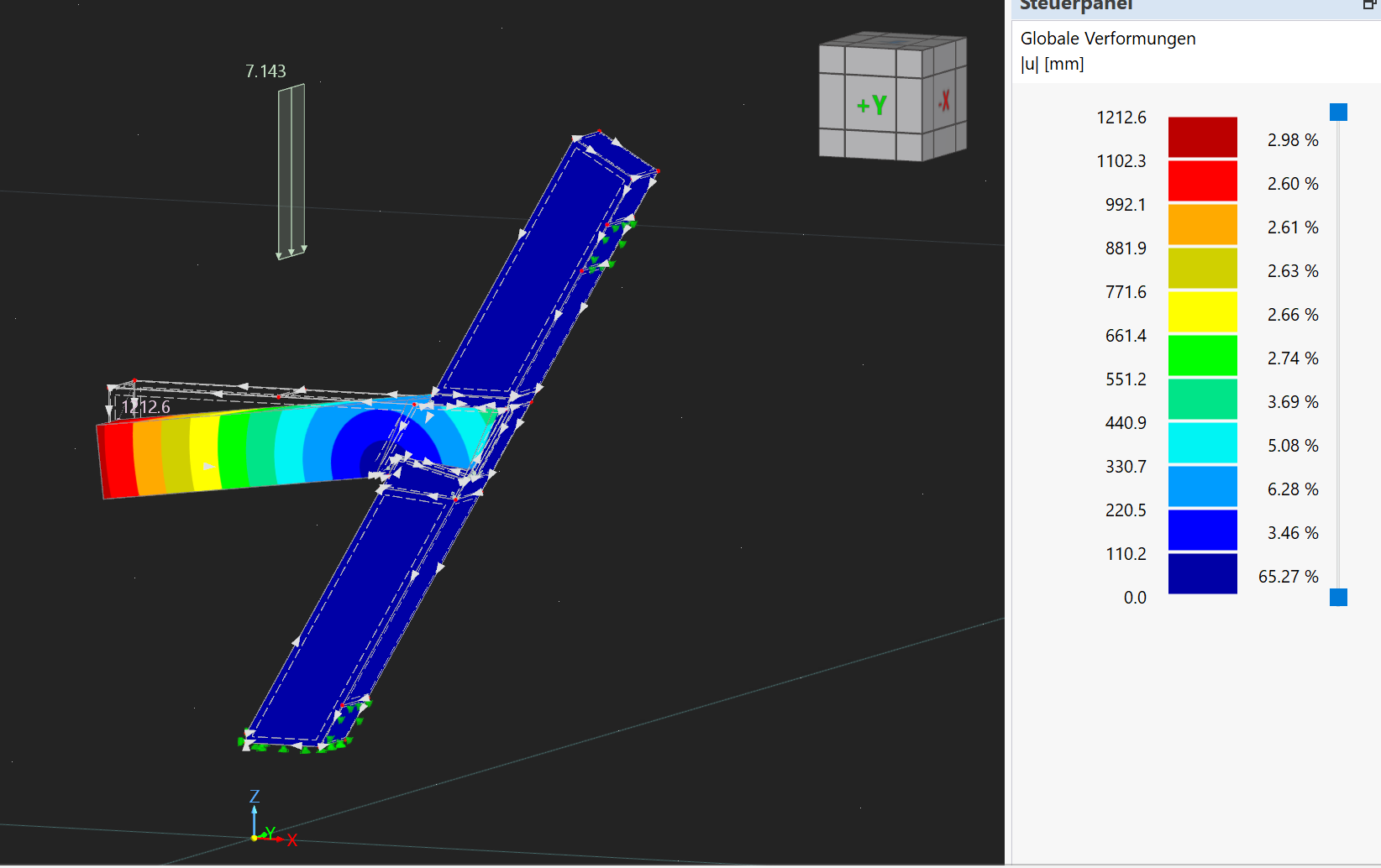
I have now taken a closer look at the model again and gone through the steps from the FAQ. When looking at the global deformations, I noticed that these occur exclusively in the component of the strut (see image). It also deforms through the chord across the contact surface. I had actually assumed that the surface contacts would also limit the deformation of one volume into another. Now I am a bit at a loss as to which definitions I need to make and am hoping again for a helpful tip.
Many thanks and best regards
Baustudi
Flächenkontakt_0.01 - Kopie.rf6 (5.9 MB)
Hello Baustudi,
Flächenkontakt_0.01 - Kopie-03.rf6 (19.8 MB)
I have reviewed the file. The problem is the definition of the surface contact. The coefficient of sliding friction was almost zero. This led to instability. In the attached file, I have enabled full force transmission. Then the model is stable.
Due to the very low friction, the model was practically kinematic. I suspect that the horizontal beam "slips out" of the connection under the load in the -Y direction.
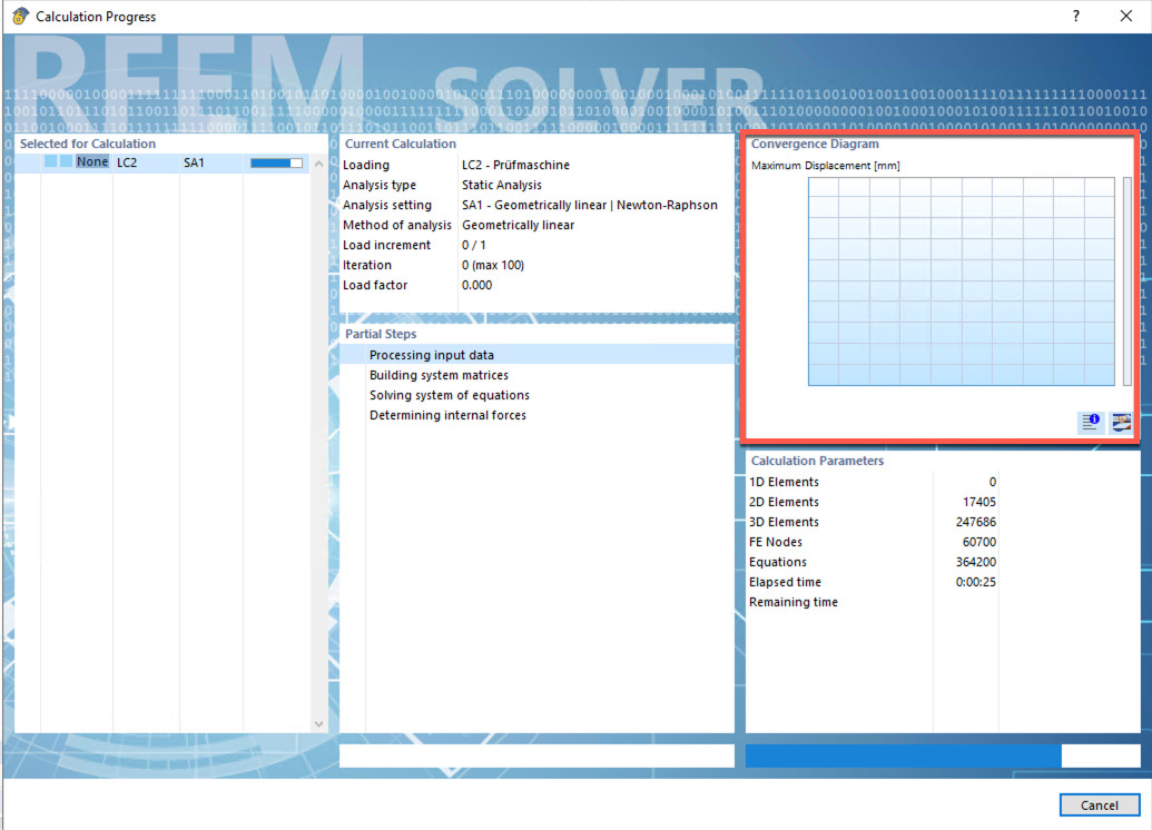
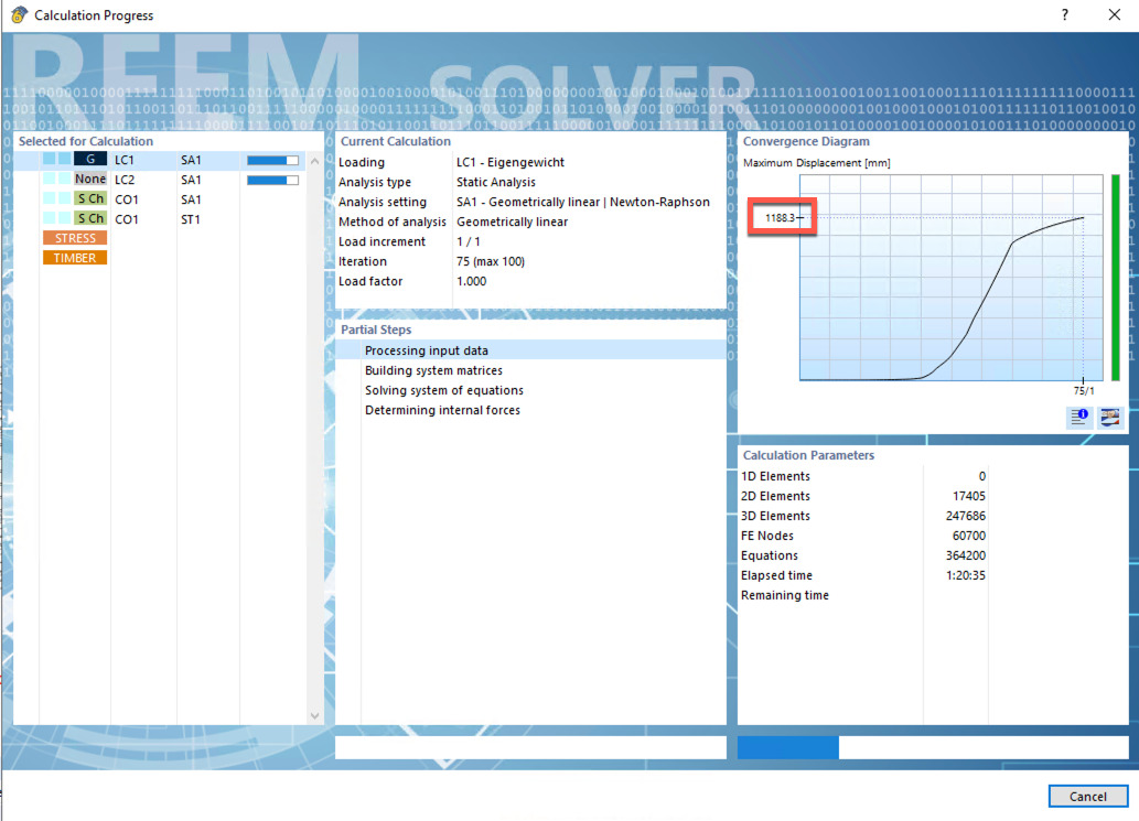
In the solver window, the convergence diagram is visible on the right side. From this, you can clearly see from when the deformation sharply increases. You also see the iteration number.
Try limiting the maximum number of iterations to this iteration in the calculation parameters. Display the deformation. In the graph, you will likely be able to see what is going wrong.
Many greetings
Frank
2 Likes
Hello Frank,
thank you very much for your response, that is definitely helpful. I just don’t quite understand what you mean in your last paragraph. Which error am I supposed to be able to recognize in the graphic then?
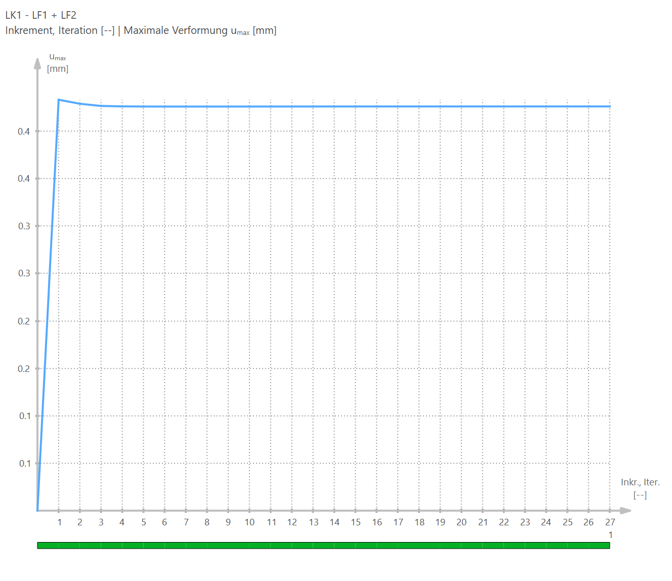
When I look at the convergence diagram, there is only a steep increase up to the first iteration step. Does this mean that this one step is sufficient for this calculation? Apart from that, a calculation with full force transfer does not make sense to me. But if I set the friction coefficient to a realistic value of 0.5 for wood, then I have the problem again that the load cases do not converge. Can I now orient myself on the previously mentioned number of one iteration step and take the deformation at this step as my result for this calculation or how do I know which deformation I can choose as my result?
Unfortunately, even with a friction coefficient of 0.55, unrealistically high deformations result.
Best regards
Baustudi
A small addition with another thought of mine: In your previous message, you wrote that the friction coefficient to be specified is that of sliding friction. Could it be that the large deformation occurs because static friction is not taken into account in this case? Is it possible that taking this into account could be done elsewhere?
Hello,
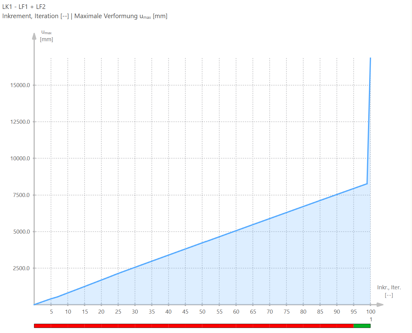
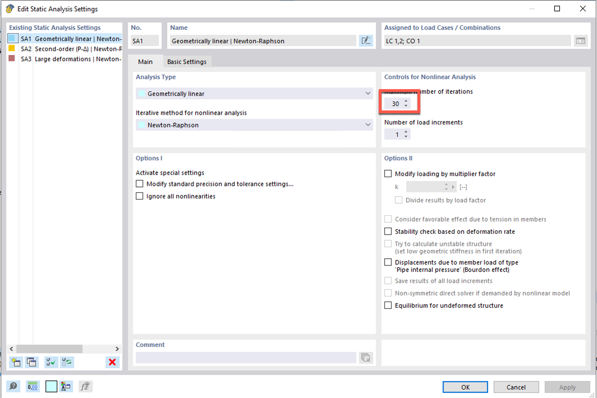
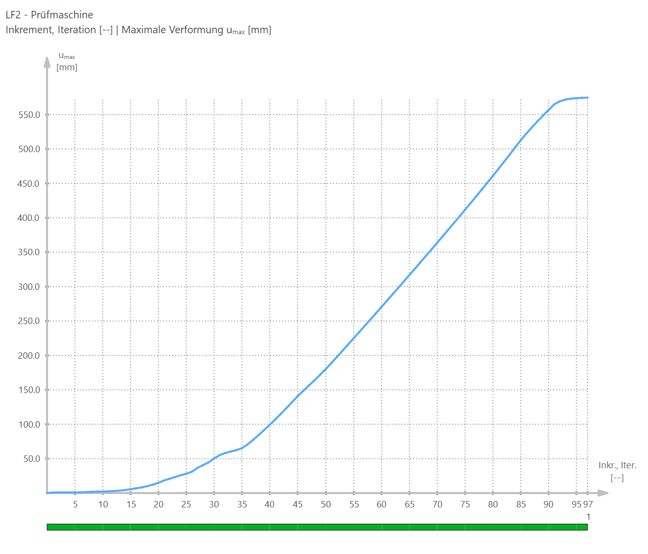
by the convergence diagram I meant this one:
In this diagram, you can see at which iteration the deformation suddenly increases steeply.
This happens at about 30 iterations. Therefore, I limited the number of iterations to 30 in the calculation parameters and then calculated load case 2.
Flächenkontakt_0.01 - Kopie-09.rf6 (5.7 MB)
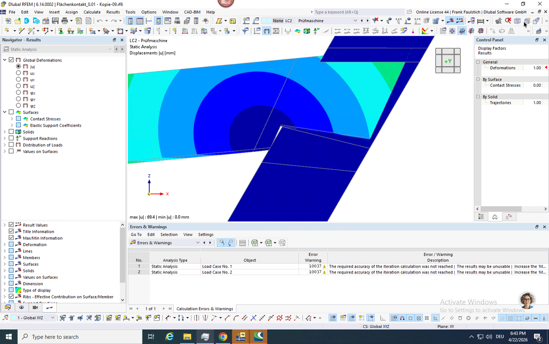
A warning then appears that the maximum number of iterations has been reached, which is intended. Then I looked at the deformation in this state:
The dovetail joint simply slips out of the inclined bar.
So the cause of the problem seems clear: everything is modeled correctly in RFEM, only the connection is overloaded.
I also did another experiment that confirms the suspicion. Instead of the orthotropic material, I used isotropic. This way, the dovetail is no longer compressed so strongly. The connection then remains stable.
Flächenkontakt_0.01 - Kopie-07.rf6 (5.7 MB)
Best regards
Frank
That is an interesting question. Simulation of static friction transitioning into sliding friction is currently not possible with the surface contact in RFEM.
If we wanted to implement that, we would have to create a combination of friction with stress limitation and with a coefficient of friction. The static friction would then have to be represented by the stress limitation. Once the stress is exceeded, the surface contact would have to transition into friction with a coefficient of friction.
As mentioned, this is currently not possible with the surface contact. If you absolutely need to model this, it could be done with small rods that are manually placed between the individual FE nodes of the contact surfaces and where appropriate releases are defined at their ends. I would only do that as an absolute last resort.
Best regards
Frank
Hello Frank,
Thank you very much for your effort and your detailed response.
My basic goal is to adjust the model so that the occurring twists match the experimentally determined values as closely as possible. Thus, I also know that the connection in reality is capable of transmitting the currently applied load without too much deformation.
With the insight gained, in my opinion, the only lever now would be friction. My idea is to choose the contact type of elastic friction for the contact surfaces and to increase the value of the shear stiffness until the model and experimental results are close to each other. I would justify this approach by the fact that in reality plastic deformations occur that lead to the indentation of the leaf into the side surfaces of the leaf seats and thus can no longer be represented by the commonly used friction parameters in the literature.
Do you consider this approach sensible from a programming perspective or do you possibly have another suggestion?
Best regards
Baustudi
Your planned approach makes sense to me.
I have the following thoughts:
- Check whether the load in load case 2 is really correct. Errors can easily occur during the conversion.
- Have a look at the stresses sigma_z in load case 2 in file 09. They seem relatively high to me.
- Do the material parameters match the experiment? Perhaps the Young's modulus perpendicular to the fiber was higher in the experiment than assumed in the RFEM model.
- You mention plastic deformations. In RFEM there is the orthotropic plastic material model (Tsai-Wu). It might make sense to use it. However, before activating the plastic material model, the model should run stably with the elastic material model.
Best regards,
Frank
1 Like
Hello Frank,
unfortunately, my idea of increasing the stiffness of the contacts did not lead to significantly lower deformations.
I have checked my load and the material model again, but found nothing unusual. The load is supposed to be 1.5 kN and is distributed over the entire width of the component. The material model corresponds to that of softwood C24, only the strength values were changed from characteristic values to average values. I am now not sure what else I can try.
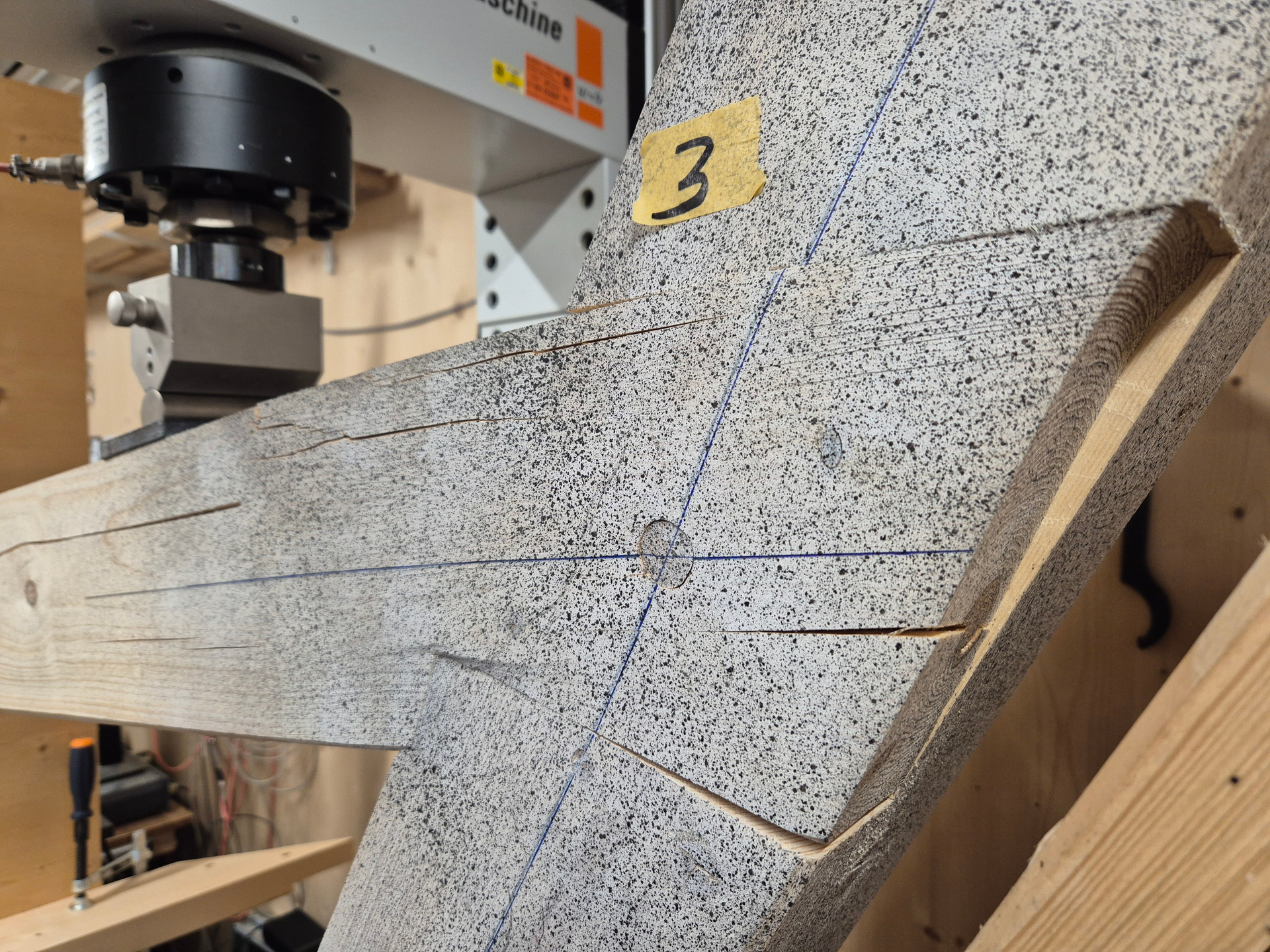
The deformation of the sheet under a load of around 20 kN (see picture) indeed shows that it was somewhat pulled out of the sheet stack, but not to the extent of the model. The maximum deformation in this test is 43 mm.
My last idea is to stop the calculation already at iteration 5-10, since from about that point I observe an increasingly pronounced rise in deformation and the deformations are within a realistic range. However, this seems somewhat arbitrary to me.
SurfaceContact_0.01 - Friction05_Copy.rf6 (5.9 MB)
Hello,
I have just discovered a problem in the file.
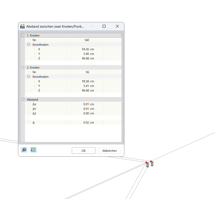
There are some places where nodes are very close to each other. I am currently trying to correct this and then run a test calculation.
Limiting the calculation to a certain number of iterations is not a solution. The results are then not usable.
Best regards
Frank
1 Like
Hello Frank,
I finally know where the problem lay: I forgot to model the contact of the leaf at the leaf socket in one place. That was probably a very simple solution; it's a pity that I didn't notice it earlier.
Thank you for your help.
Best regards
Baustudi
1 Like