hello everybodey,
I just install a Trial version of RFEM Dlubal 6, for designing a steel structure as shown bellow
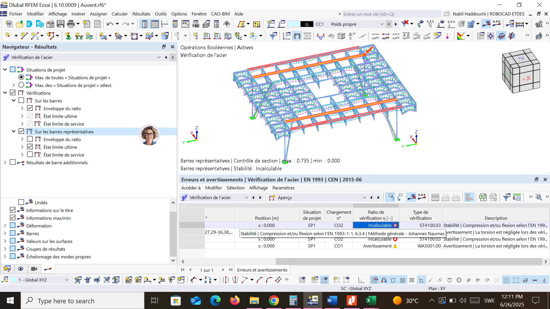
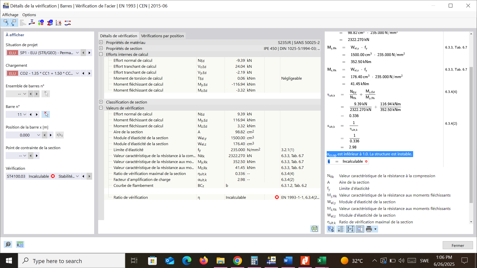
Whene i go de design steel, i got an message erreur as shown in the piscture above
Could you please help me
Sincerly
hello everybodey,
I just install a Trial version of RFEM Dlubal 6, for designing a steel structure as shown bellow
Whene i go de design steel, i got an message erreur as shown in the piscture above
Could you please help me
Sincerly
Hi HADDOUCHI,
welcome to our Dlubal Community! ![]() We are glad to have you here!
We are glad to have you here!
Could please post the model file or send it to me via personal message (click on my name and select message), so I can take a closer look? There are multiple possible reasons ...
Thank you for the model files.
![]() Analysis
Analysis
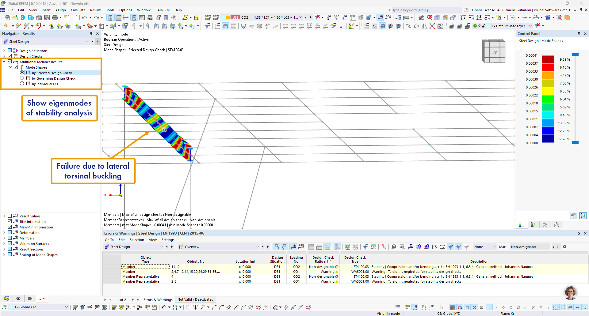
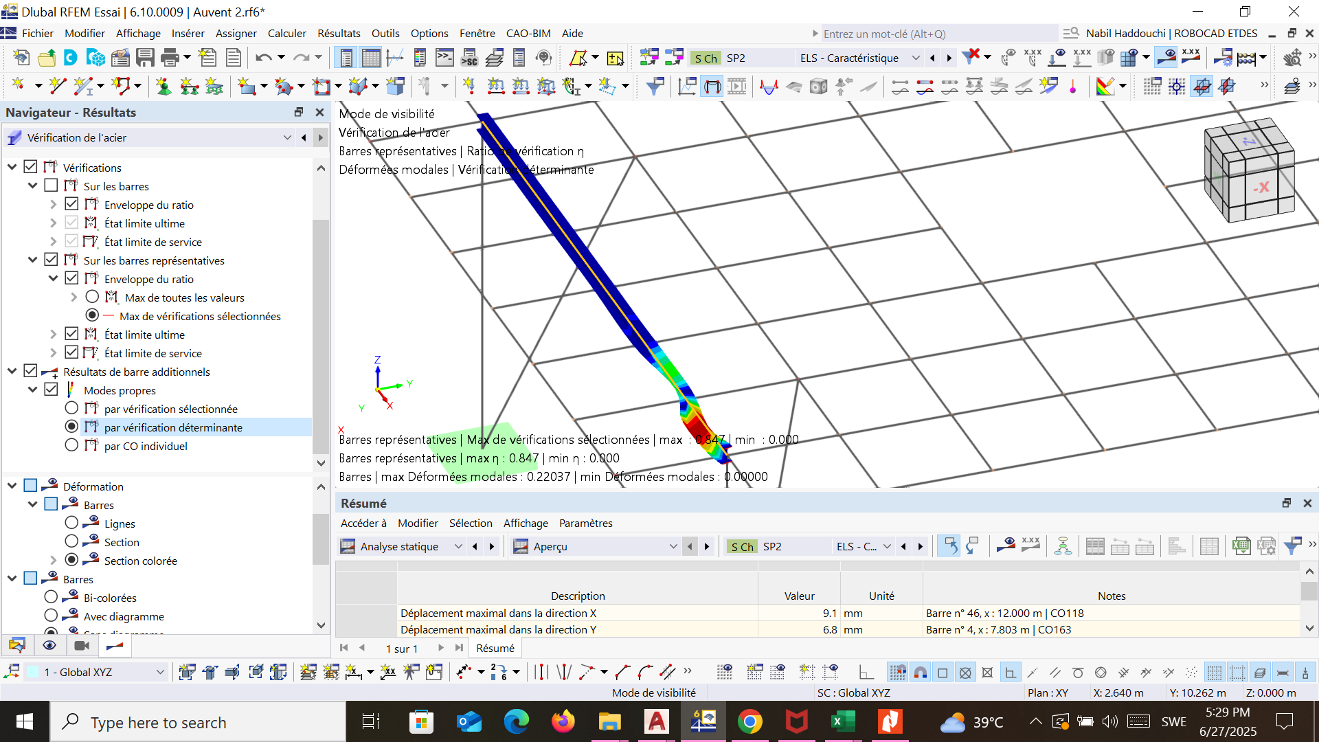
The reason for the issue is rooted in the stability failure due to lateral torsional buckling of the affected members. You can display the eigenmodes in the result navigator:
![]() Solution
Solution
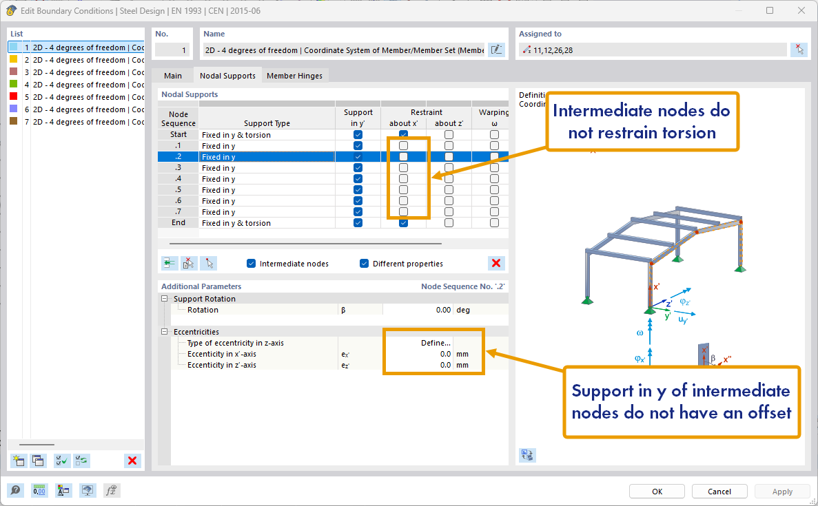
To solve this, you have to either activate the torsional restraint (about x) or define an offset for the lateral restraint (in y), e.g. the upper flange, for the intermediate nodes
If you have any questions, just write to me. I'm happy to help.
I m very happy to see your answer
I realy see the lateral torsional buckling in the member you selected
For the fisrt solution (Restaint the torsion about x), it is easy to do by selecting all intermidiate nodes, but i don't kniw in this case how my assembly will seems like
About the second solution i realy don't know how to process, but i choose the same hight memeber for both memebre and restraint, so i tooth offset in not realy helpfull
Think you again and agin sorry my english is bad
Thins
Hello,
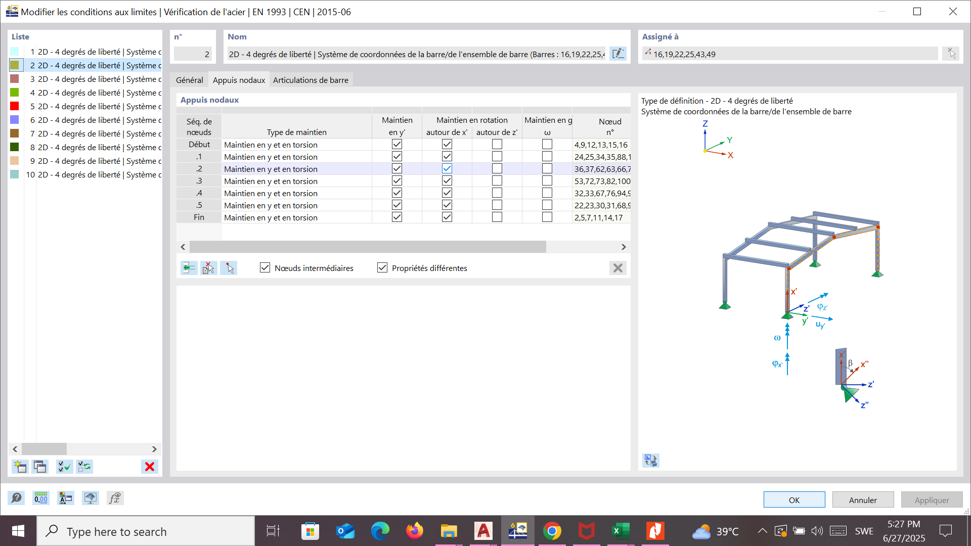
As you ask me, i turned on all torsional restraints about x
then imy memebre stability seems like this:
Sincerly
Hello,
I still have a lateral torsional buckling in the end of my member
Sincerly
The assembly probably would need to contain some stiffeners so that it is appropriate to assume a rotational restraint.
Usually, yes, because the purlins are located normally above the beam girders. Generally, it depends on how the construction design looks like.
The two members do not have to be in different planes for this because the stability calculation for the bifurcation loads is performed internally with a submodel that uses the boundary conditions provided in the dialog instead of the global model.
This looks plausible
Hello,
Think you very much for your answer
I my case, the member and the stiffners are in the same plane and should have the same hight in order to atach on them an upper and lower perfored aluminium plate
For your second answer, i can understand that the calulation of the modele are maken taking the bouandry limits in the table, and not from the type of connexion in the general model
My last point, is i still have a lateral torsional buckling in the end of my member even if i block the torsional buckling arround x, i attend not to have any torsional bucklung in my members. is this situation correct
Sincerly
Yes. The rotational restraint is only present at the intermediate node, so the member can still buckle betwee two nodes.
hello agian
OK THINK YOU VERY MUCH, ANY WAY MY RATIO IS O.847 < 1 SO I THINK IT IOS OK
sincerly
9 posts were split to a new topic: Meaning of color scale for mode shape
Hi HADDOUCHI,
Each topic should only deal with one specific question, so I have created a new topic and moved your last posts. You can find the link above this post.
![]() More information: How to Get Quick & Helpful Answers
More information: How to Get Quick & Helpful Answers
Best regards ![]()
Clemens Gutmann
Think you very much for this arrangement of my last posts
Sincerly
Think you very much for this arrangement