Hello dear community,
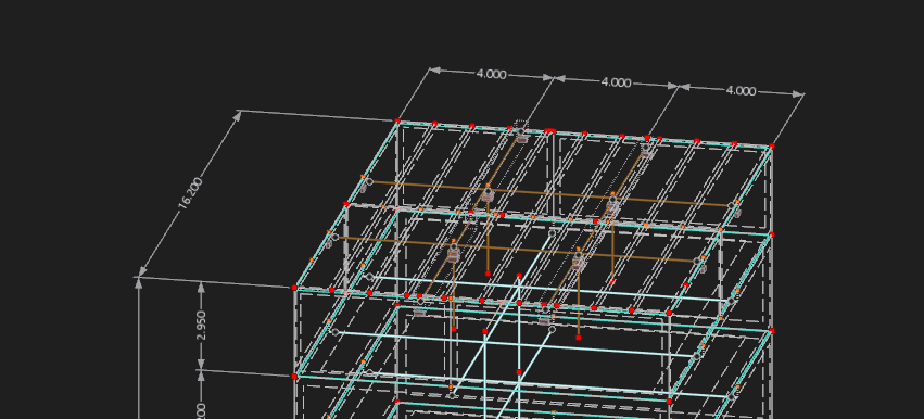
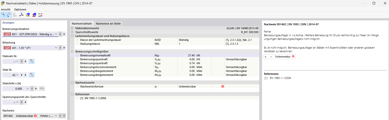
I have another question regarding my work. Yesterday, Mr. Gebhardt corrected my topic concerning cross-laminated timber (CLT) elements and the missing kmod or use classes. Now I am supposed to present different variants of the timber structure for my work and thought to stay as close as possible to the original reinforced concrete model by using wooden beams/girders located under my CLT ceiling. Since I had to split the ceiling (L x W = 16.20m x 12.00m) into smaller sections (20 times 8.10m x 1.20m CLT elements), can I never select a corresponding first surface if I choose a member as a rib member? I also tried to model a beam member with eccentricity and design supports, but I received an error message that the design support does not work for members with eccentricity. Could you help me on how to proceed?
I would really appreciate a response.
thank you very much for your inquiry.
I am not quite sure if you still need the design support. But if you really want to use it, you can connect it via a 'rigid coupling'. I am attaching your model here, where I have changed it on a rod accordingly BSP_Modell_Bemessung_Obergeschoss-30.04_Unterzuege-Community (1).rf6 (1.8 MB).
Thank you very much, Mr. Kuhn,
that already helps me a lot. When do you need the design support?
You would then probably have to apply it to all 4 beams, right? And regarding the inserted line hinge with cux=6000 kN/m^2, is that some kind of standard value or was it simply freely chosen by you?
Best regards
Linus Högel
The design support is always used to carry out the transverse compression verification. Shear force reduction and special requirements on the deflection might also be a reason.
When roughly looking through the model, I could not see that the transverse compression verification becomes relevant here. Therefore, I would not have defined the design support everywhere and, if at all, only at the most highly stressed location.
The displacement of the line hinge corresponds approximately to an 8x160 screw screwed about every 33 cm over one meter, on a characteristic level.
The topic is also addressed in the following posts.