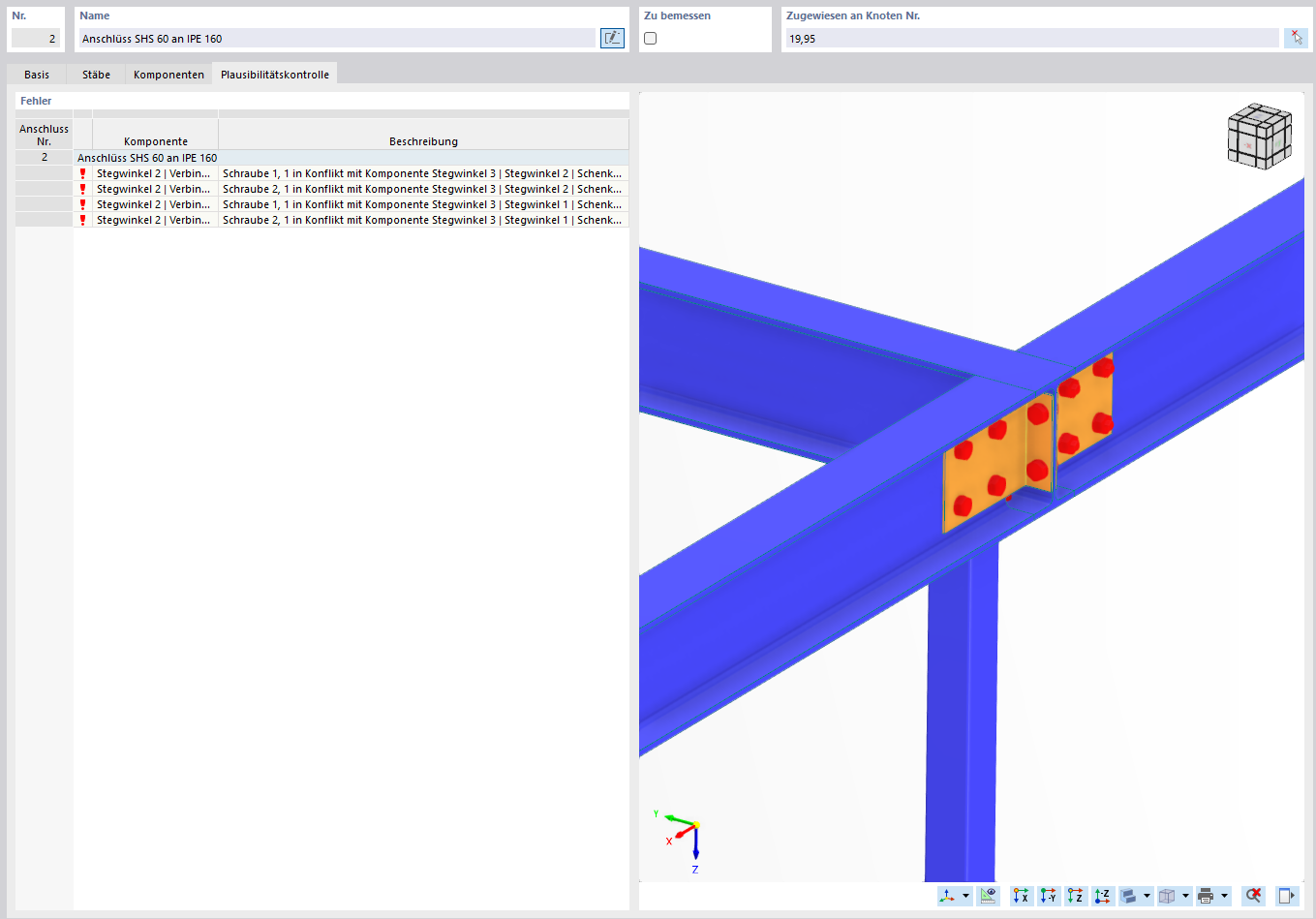
When editing a steel connection in RFEM 6 (module Edit Steel Connection), I repeatedly receive the following error messages:
- Bolt 1 in conflict with component web angle 3 / web angle 2 (leg)
- Bolt 2 in conflict with component web angle 3 / web angle 2 (leg)
This concerns the connection SHS 60 to IPE 160 (see attached screenshot). Despite adjusting the bolt rows, the conflict still occurs.
Could you please let me know
- whether this is a setting error on my part or a known issue in the module,
- which adjustments (bolt position, geometry of the angles, alternative connection type) you recommend to model this connection correctly?
Attached you will find the model file as well as a screenshot of the error message.
Thank you very much for your support!
Hi Mzabi2025,
Hello and welcome to the community! 
Thank you for your message!
To analyze the problem more precisely, the model file would be very helpful:
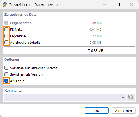
 Click on File → Save As and choose the following settings to reduce the file size:
Then upload the file here (e.g. *.rf6, *.rs9) – this way the community can also contribute to the solution.
 Don't want to share the file publicly? No problem – send it to me via direct message: click on my profile picture or my username → Message.
Best regards
Stefan Hoffmann
Hi Mzabi2025,
Thank you very much for the model!
Currently, there is an input issue here. To ensure the connection works correctly, a few adjustments are still necessary:
-
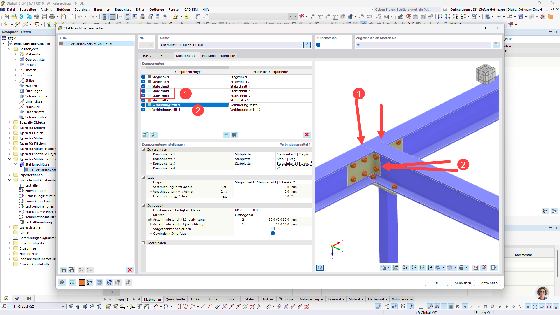
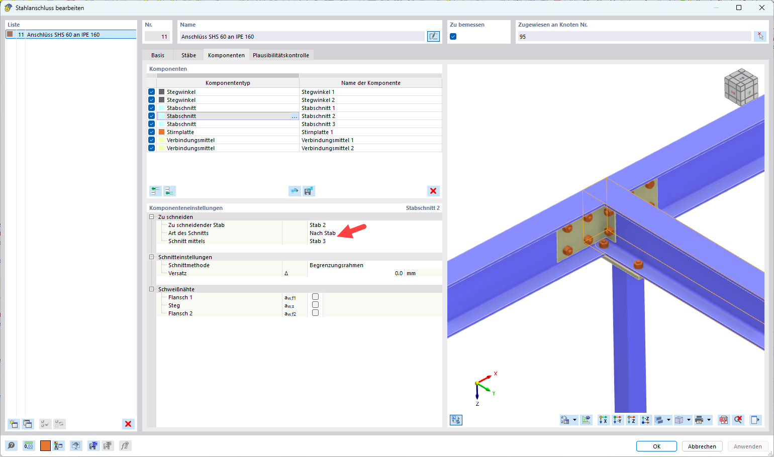
Please insert two additional beam sections.
This will ensure all beams are properly cut, which forms the basis for the subsequent connection.
-
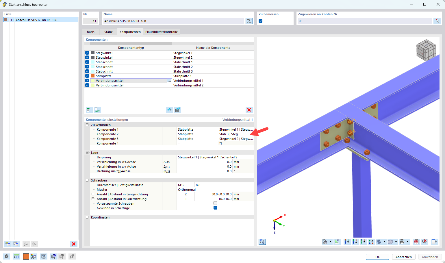
The screws of the web angles by default always connect only two components.
In your case, however, you want to connect three components, which is not automatically possible.
Solution: Define the screws manually at this point.
This bypasses the limitation – and the connection works as desired  .
.
If you have any further questions or need support with the implementation, we are happy to assist you! 
Best regards
Stefan Hoffmann
Could you please show me how I can make the two additional staff sections, and how I can insert the screws manually.....
Should the step angle be inserted without screws?
Hi Mzabi2025,
We are happy to support you with the modeling of your project. However, please understand that detailed explanations tend to have the character of a training session and are not part of the regular support.
Regarding your request:
-
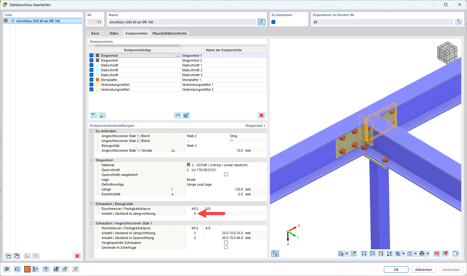
Deactivate the screws on the reference rods
For both web angles, proceed by deactivating the screw connection on the reference rods.
-
Add two rod sections
You need these so that Rod 2 and Rod 4 are separated by Rod 3. This creates the correct geometry for the connection.
-
Add the screws manually
Place the screws so that they pass through both web angles and Rod 3. This ensures the connection is mechanically modeled correctly.
 With these steps, your connection should work as desired.
Best regards
Stefan Hoffmann
Great, thank you very much for the help 
1 Like