I’m running into an issue with the shear resistance check according to EN 1992-1-1 (formula 6.2.a). In some locations the software sets the tensile reinforcement area Asl to zero, even though the reinforcement is clearly present.
Here’s what actually happens:
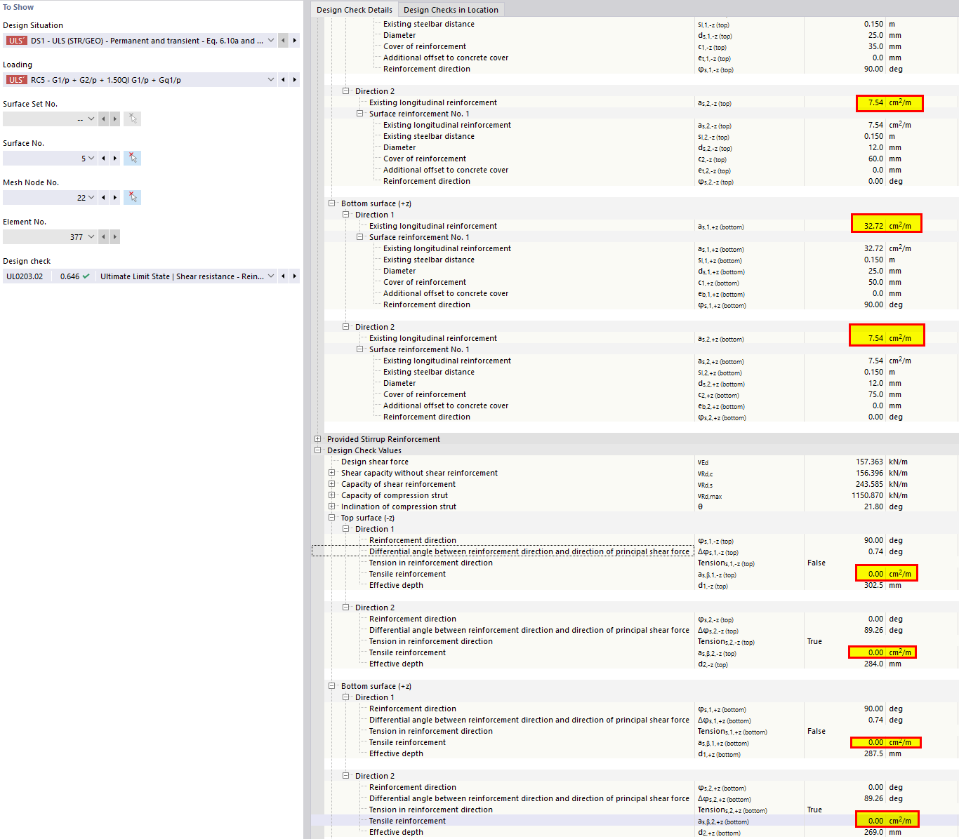
At several mesh nodes, usually right at the edge of the shell, the program reports Asl = 0.
It does this in all reinforcement directions, no matter whether the angle to the shear force is 0° or 90°.
Once Asl is zero, the shear resistance drops to the minimum value from 6.2.b, and the section fails the check.
My only guess is that the software assumes the reinforcement at the boundary is not anchored long enough beyond the section, because the model physically ends there. So it might be deciding that the bars don’t satisfy the required anchorage length (lbd + d), and therefore Asl doesn’t count. But that’s just speculation on my part.
Thank you for your message! The behavior you observed in the shear check of your model is caused by two main factors:
Shear design without shear reinforcement (Eurocode 2)
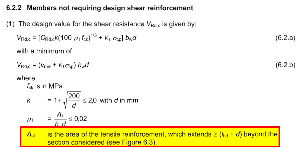
As highlighted in your image, the standard allows longitudinal tension reinforcement to be considered in the calculation of shear resistance. Therefore, if the entire wall section is under compression, the tension reinforcement ratio is treated as 0. This explains the behavior you observed in the shear check.
Line support modeling
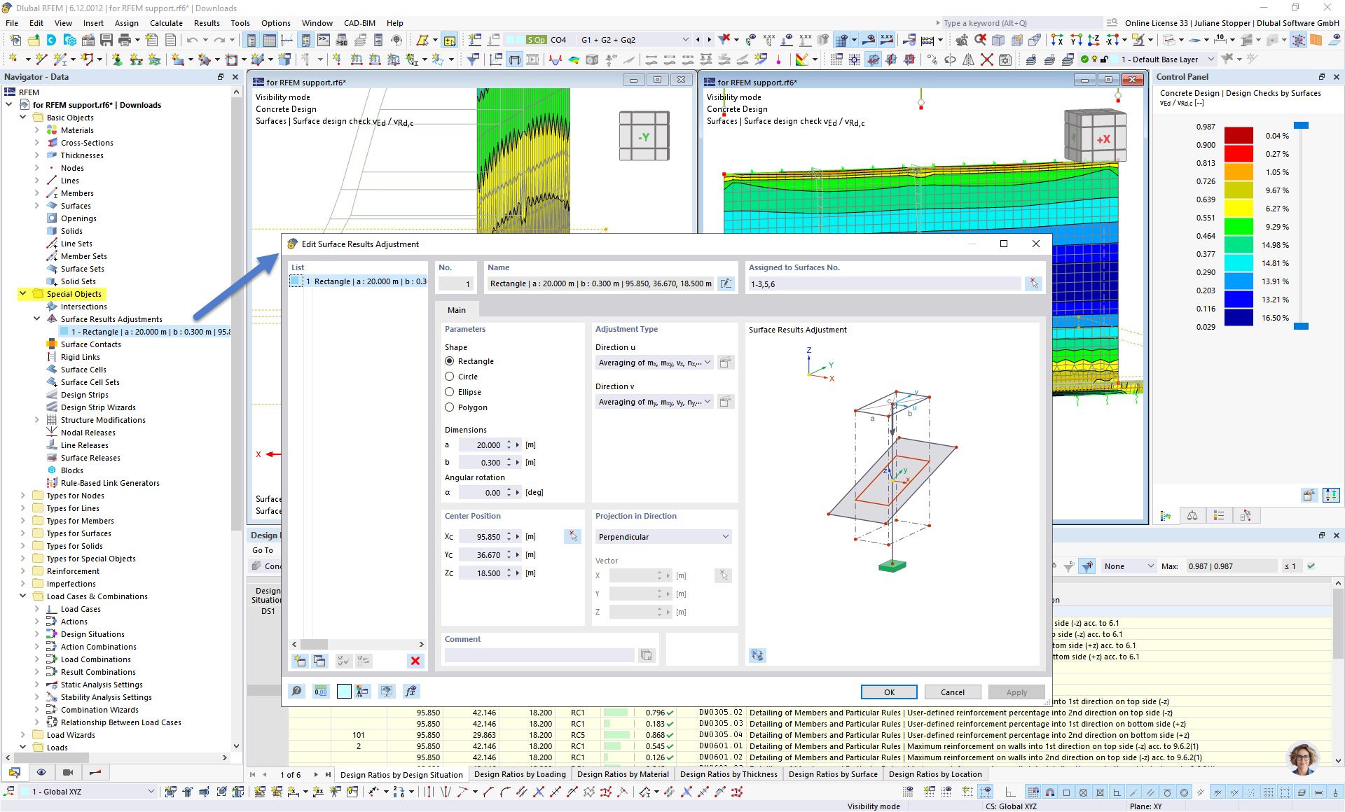
To improve the model behaviour, I:
Added a surface result adjustment with a height of 0.3 m (as you had defined in the supports dimension) to model a more realistic load transfer at the support location
Improved the mesh by applying line mesh refinements
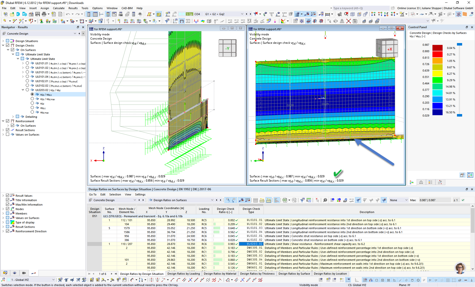
After these adjustments, the model behavior improved at the line support, and the design checks are now fulfilled. See images below.