Dear Dlubal Support Team,
I am currently working with RFEM 6 and have a question regarding the stability verification according to Eurocode 3 for cold-formed double sigma profiles (Sigma 200).
Specifically, it concerns:
- Double sigma profiles, bolted from two sigma profiles
- alternatively double U-profiles, bolted back to back
- cold-formed profiles according to EC3
- application within the scope of a global stability verification (buckling/torsional-flexural buckling)
In the standard (e.g., EN 1993-1-1, section 6.3.4), the general procedure is explicitly formulated for I-profiles.
Additionally, there is the substitute member verification according to 6.3.2.
My specific questions are:
- How is the stability verification for double sigma profiles carried out in RFEM 6 in accordance with the standard?
- Is the substitute member verification according to 6.3.2 permissible for such profiles, especially under combined loading (N + M)?
- Is it recommended to perform the stability verification via the global model (second-order theory with imperfections)?
- Is there a recommended modeling and verification strategy in RFEM 6 (e.g., member model vs. FE surface model) specifically for cold-formed double profiles?
I would be very grateful for a brief technical response or possibly a reference to:
- Dlubal manuals
- Knowledge base articles
- Tutorials or example models
Thank you very much in advance for your support.
Hi Mzabi2025  ,
,
thank you very much for your inquiry! 
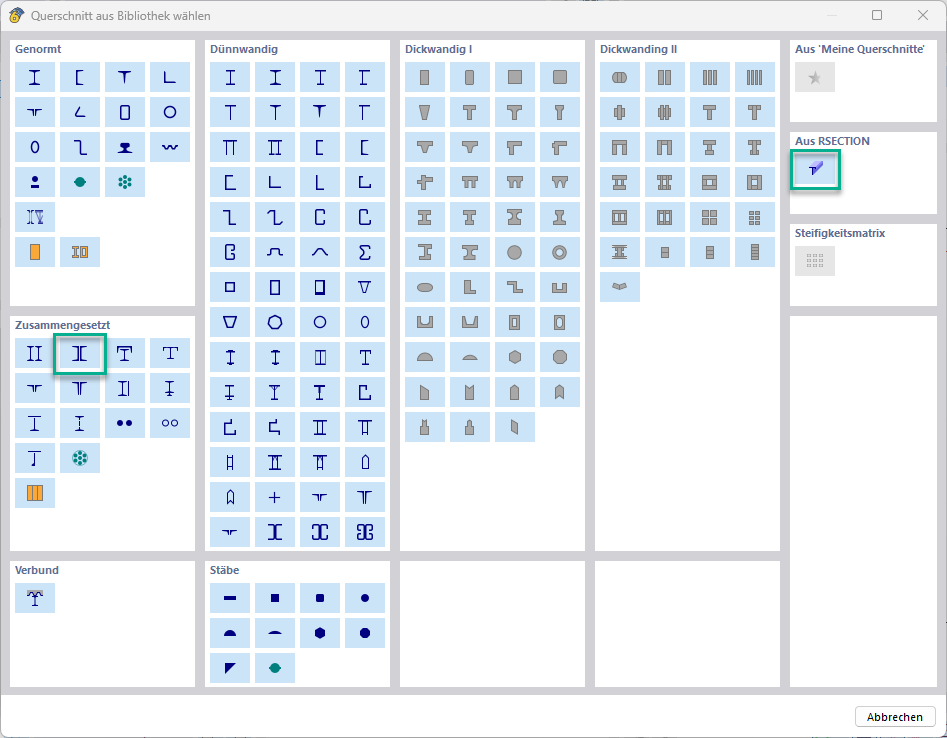
Unfortunately, we do not offer double sigma profiles directly in the cross-section library. However, you have the option to use a composite U-profile  . Alternatively, you can also create a double sigma profile with RSECTION.
The equivalent member verification according to 6.3.2 is only applicable for pure uniaxial bending stress. For a combination of M+N, unfortunately, you cannot use this verification  . Also, according to sections 6.3.1 and 6.3.3, the boundary conditions for the equivalent member method are not met in your application case, so this verification method is generally not applicable.
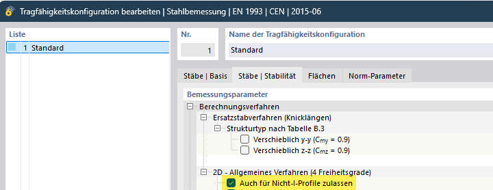
To apply the general method according to 6.3.4, you would need to activate the option "Allow also for non-I-profiles" in the load-bearing capacity configuration  . However, as you have already mentioned, this option is not permitted according to the German national annex (but it is allowed according to CEN
  ).
).
If you have to perform the verification according to DIN, the only remaining verification method is via the global model  using warping torsion, global and local imperfections, second-order theory, and the γₘ₁ factor. This method is universally applicable for any cross-section types and load combinations.
Further information on this topic can be found on our website:
I hope this helps you! If you have any further questions, I am happy to assist. 
Best regards
Niklas Wanke
1 Like
thank you very much for the time
1 Like
2xSigma 200 mit element.rsc (1.1 MB)
is that correct??
Hi Mzabi2025,
I have looked at your RSECTION file and would like to give you some recommendations:
-
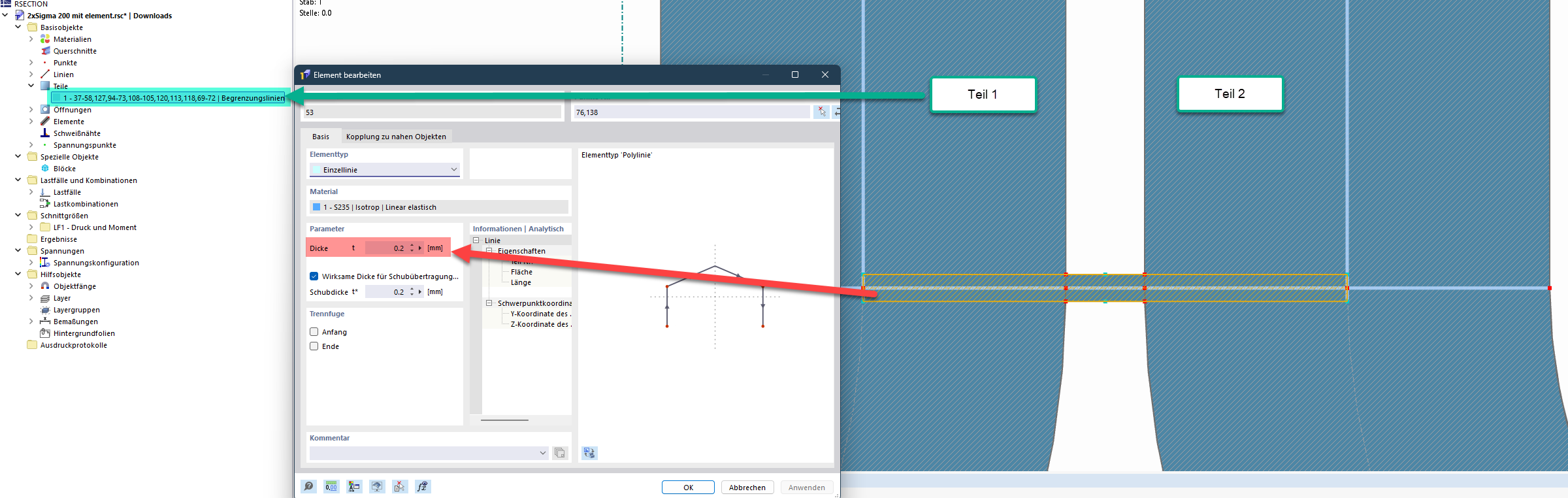
Shear elements: Set the thickness of the shear elements to t = 0. Only enter a value greater than 0 for the shear thickness t*. This way, the single field on the shear element, which is not meaningful for the cross-section classification at this point, will also disappear.
-
Sigma profiles: It would be advisable to create a separate part for each of the two Sigma profiles. Currently, you only have one entire part that also takes into account the cross-sectional area of the shear elements. Even though this area is only a small proportion in your case, it can lead to a distortion of the cross-sectional values on the unsafe side in other projects.
I hope these hints help you! If you have any questions, I am happy to assist.
Best regards
Niklas Wanke
1 Like