Hello everyone,
I am a student at Coburg University of Applied Sciences and currently working on my study project: the design and calculation of a steel pedestrian bridge.
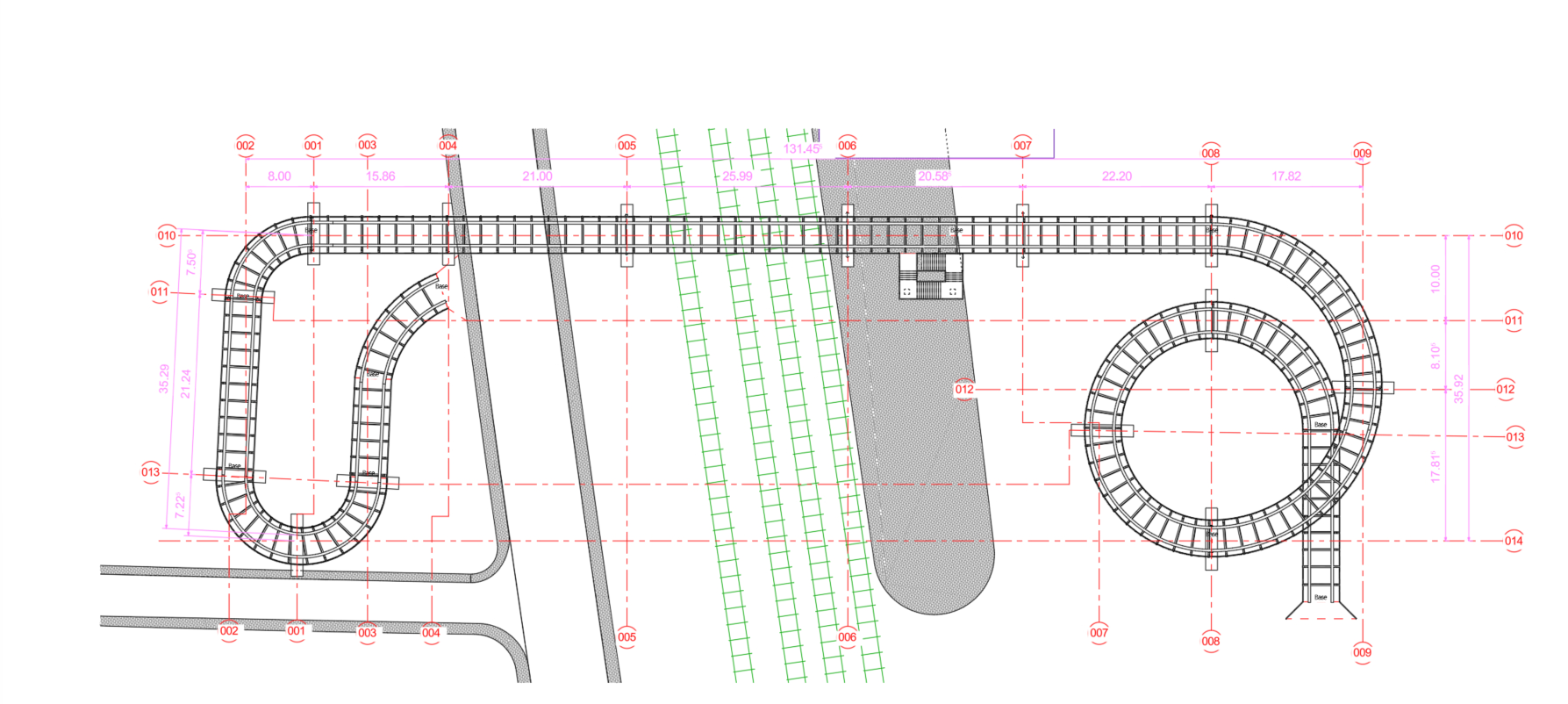
As you can see in the attached overview plan (image_2.png), the structure consists of a straight main span that transitions at both ends into complex, curved ramps (an S-curve on the left side and a spiral ramp/helix on the right side).
Since I want to model the entire structure completely in RFEM 6, I am facing some methodological questions and hope for your support or best practices:
- Modeling the curves and geometry: What is the best approach to accurately create the 3D geometry of the ramp-shaped, ascending curves and the helix in space? Is it advisable to import the centerlines directly from my DWG/DXF file (e.g., as a CAD background layer or direct import), or does RFEM 6 offer internal functions (such as formula-based node generation) that are more stable for this?
- Beam vs. surface elements: For the main girders and the bridge deck: Should I work purely with beams and eccentricities here, or is modeling the roadway slab as a curved surface (shell) more reasonable to correctly capture torsion?
- Coupling of components: Which joints or couplings are recommended for the transition between the rigid, straight bridge part and the more flexible, curved ramp structures?
I have attached my current DWG plan as an image. I would greatly appreciate any tips, workflows, or references to similar Dlubal webinars/tutorials on bridge construction and complex geometries!
Thank you very much in advance for your help.
Best regards,
Martial Edoung