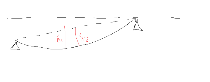
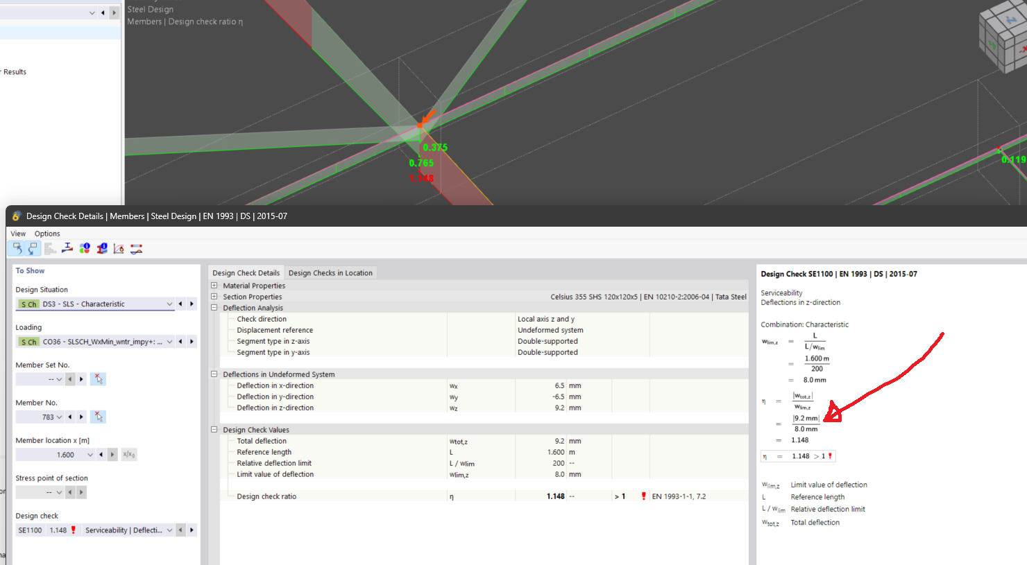
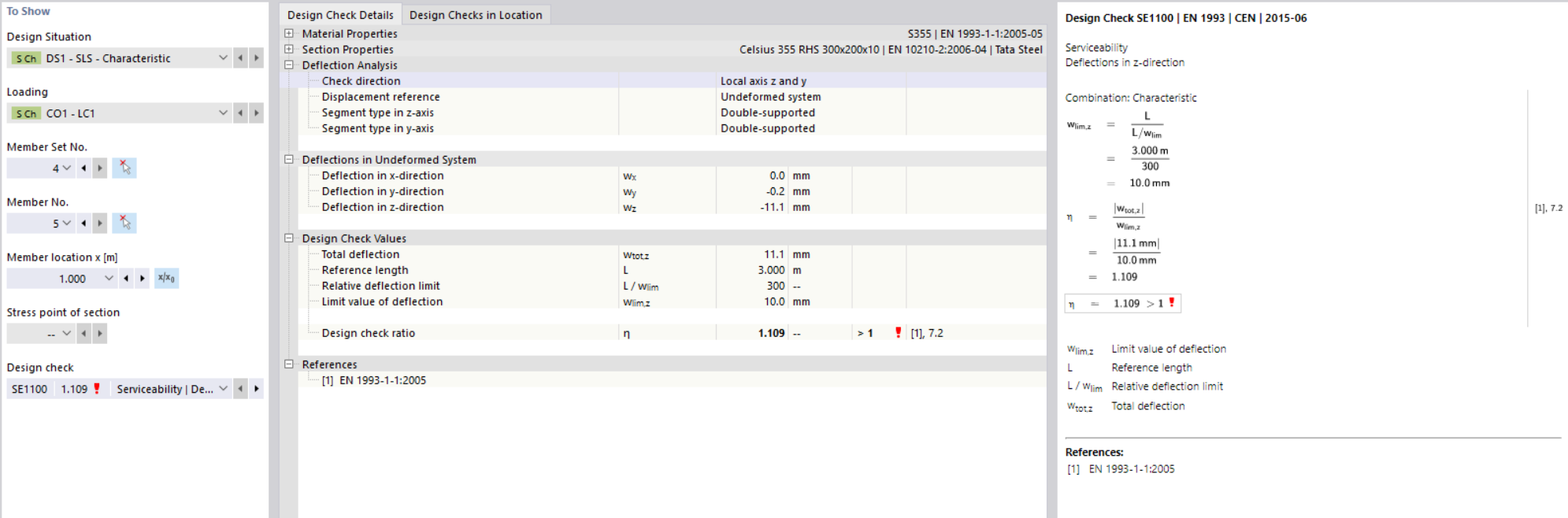
The steel design add-on uses a "relative" deformation limit (e.g. L/200) and compares it with the maximum global deformation (delta1 in image below) for the SLS design check.
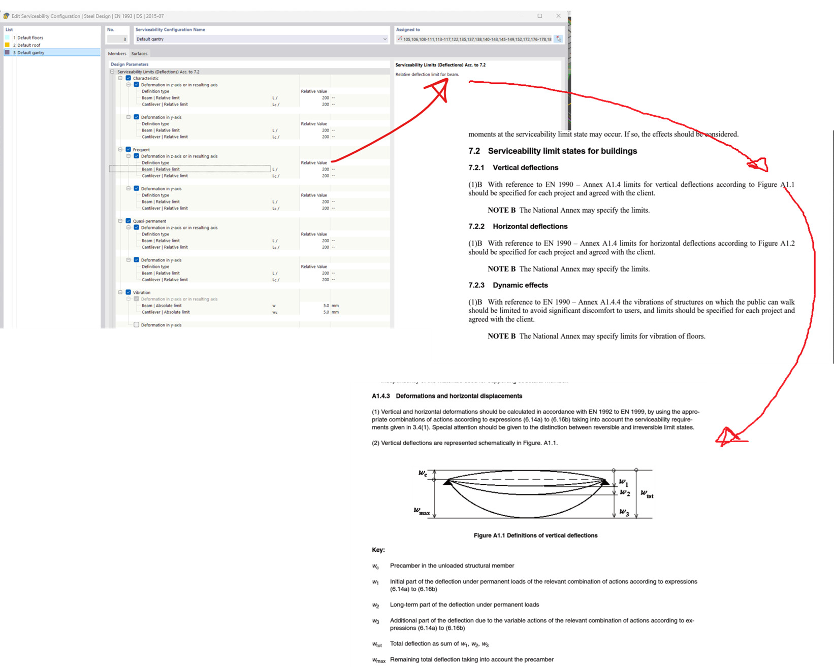
settings of the SLS design check and tracing of the address in the Eurocode given by the steel add-on shown below. The Eurocode image only defines local/relative deformation of the member.
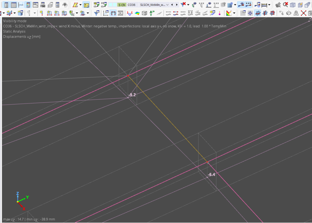
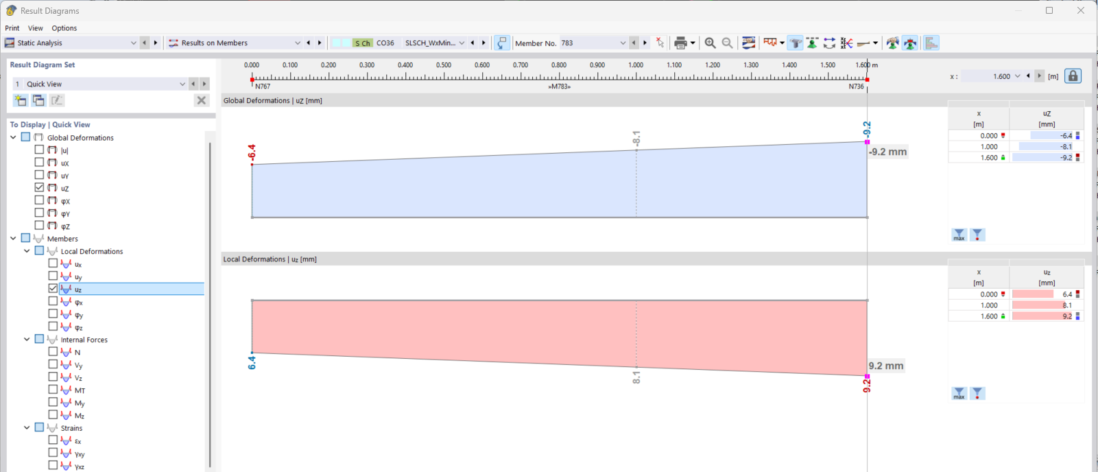
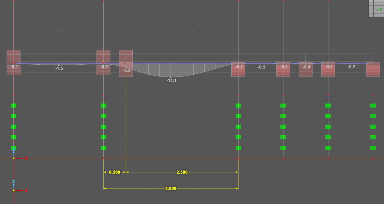
global and "local" displacement values in diagram view. Local is only given in the member local coordinate system, not really a relative deformation. (how to even see it?)
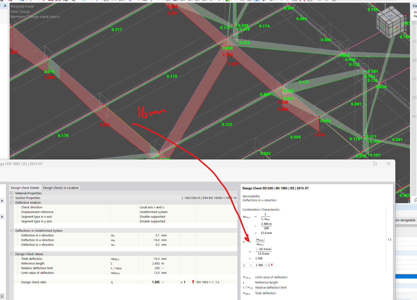
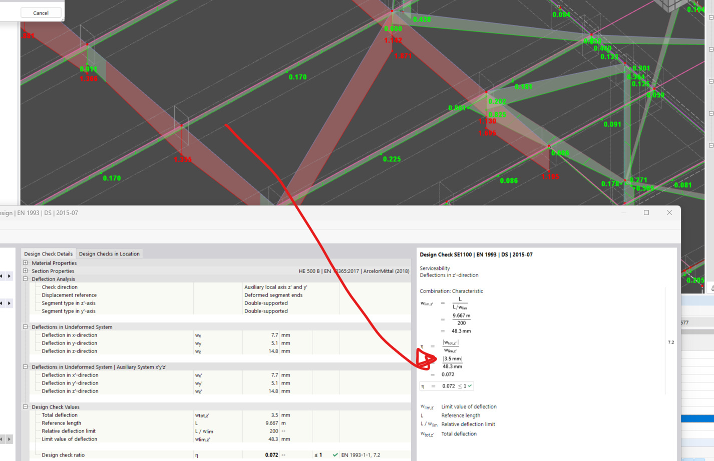
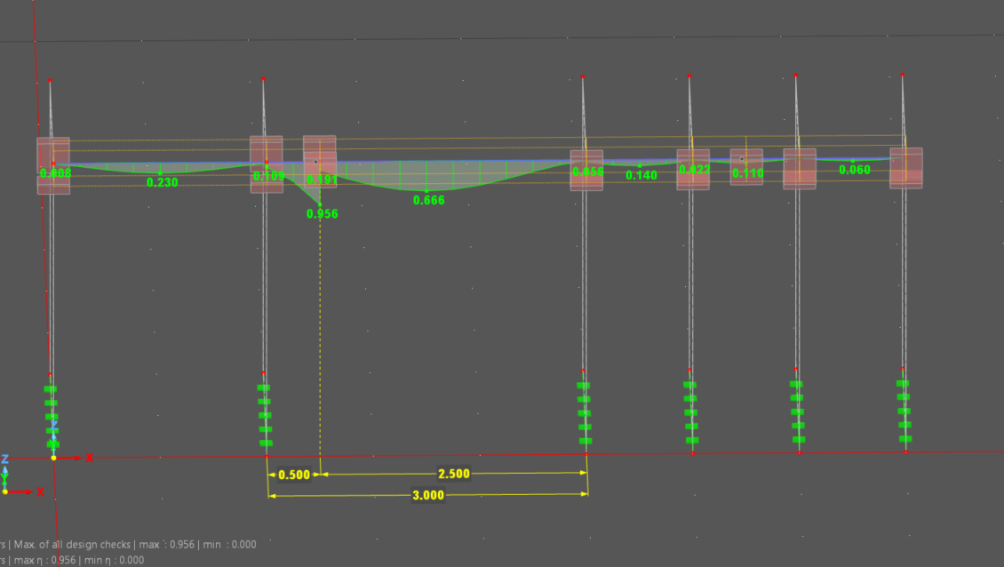
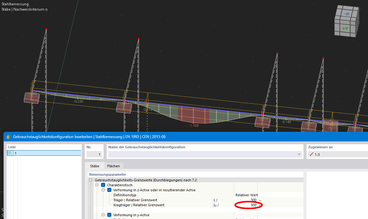
the bigger problem happens when the same SLS deflection design check gives different design ratios for two members that are connected to the same point: one design ratio is 1.35 and the other is 0.07 as in the images below.
Your post does not include any screenshot or detailed description of your current settings related to the displacement reference of the members.
Please double-check your configuration related to this setting.
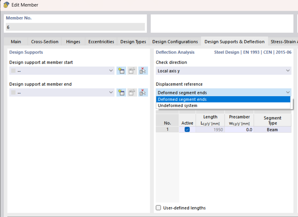
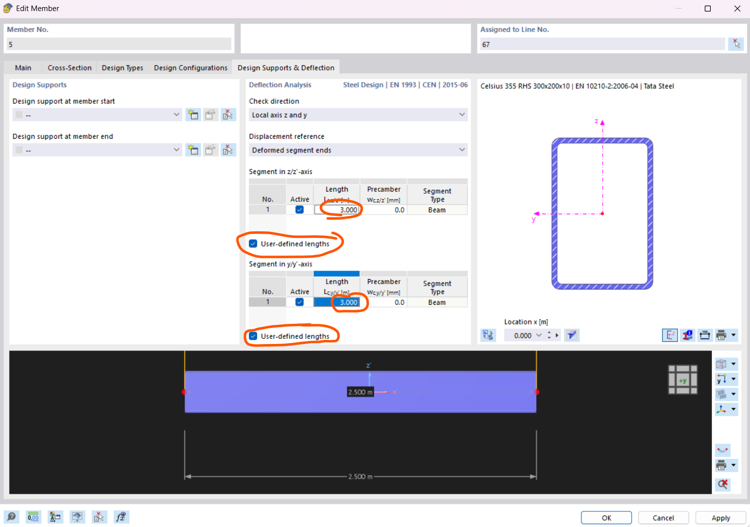
I believe you can change between relative and absolute displacement check if you change the Displacement Reference option in the Design Supports & Deflection configurations of the member
The attached example model, tests an example of design supports. The mid-span deflection of a 3m-wide span deflection is 11.1 mm which is bigger than the limit value of L/300 = 3000 /300 = 10 mm
There are two member sets meeting each other to the left of the mid-span with a hinge. I defined design supports at both ends, and applied SLS check to them. The check is not picking up the exceeding deflections.
Because of the hinge in the middle, there cannot be a continuous member set across the span. So then how to model this situation so that the steel designer detects to exceeding deflection in the floor?
In order to analyze the deflection of the mid-span with steel design, you can create a new member set with the members that form the mid-span (members 2 and 5 of your model).
Thanks for the suggestion of the adjustments that help get the correct results.
Things about these approaches that come to my mind:
1- they are more patches to go around the problem
2- the adjustments define member sets or member lengths which are different from the "physical" geometry defined in the model. This difference, could in large models be overlooked, cause confusion, hard to track when revisiting the model later, or more commonly, during the evolution of the design when the structure constantly changes, keeping track of these extra member sets, or hard-typed member design lengths, or re-implementing them causes headaches.
3- they are case-specific and are only suitable to be applied manually to a limited number of cases. In a large and complex structure, it is not practical and time-efficient to do these patches to each and one of the cases. They are even hard to implement via API automation.
4- A large number of such 'phantom' member sets created to capture the span deflections could crowd the list of member sets, and create confusion about which member set is what.
5- What is the correct definition of a member set? what is it meant to represent? does a hinge justify a break in the member set into two pieces? The Dlubal website says a member set should only not have branches. But what about hinges? what about change in cross-section, and so on. Do 'phantom member sets need to be created as overlaps on acutal member sets, to capture span deflections?
There are three potential solutions for this issue:
Use one member set over the entire length.
Create an overlapping member set for the desired span and assign an SLS configuration to it. For the remaining member sets, assign only the ULS configuration.
Use a user-defined length and modify the cantilever limit within the SLS configuration.
There isn't a fixed "correct" definition for a member set when it comes to real components. The member set itself is a tool to help define the component, rather than directly representing a physical entity. Since design properties are assigned to a specific member set, there cannot be a direct connection to a neighboring member set. To achieve that, an additional "SLS member set" would be needed (then we're back to point 4.).
If I were to suggest the best approach, I would recommend going with Solution 1, as it simplifies the process and ensures consistency.