Hi all,
the issue is related to RSTAB 8 (probably to RFEM5 too) via the COM API (RS-COM). Since this old API does not expose the member local axis vectors directly, when we read data during the import, we reconstruct each member's default local coordinate system (rotation β = 0) from its node coordinates, following the conventions described in your Knowledge Base article "Member Rotation Angle": local z in the vertical plane through the member for general members, and y parallel to global Y for vertical members.
Issue we experience: for members that are almost, but not exactly, vertical, our reconstructed axes can differ from what RSTAB displays.
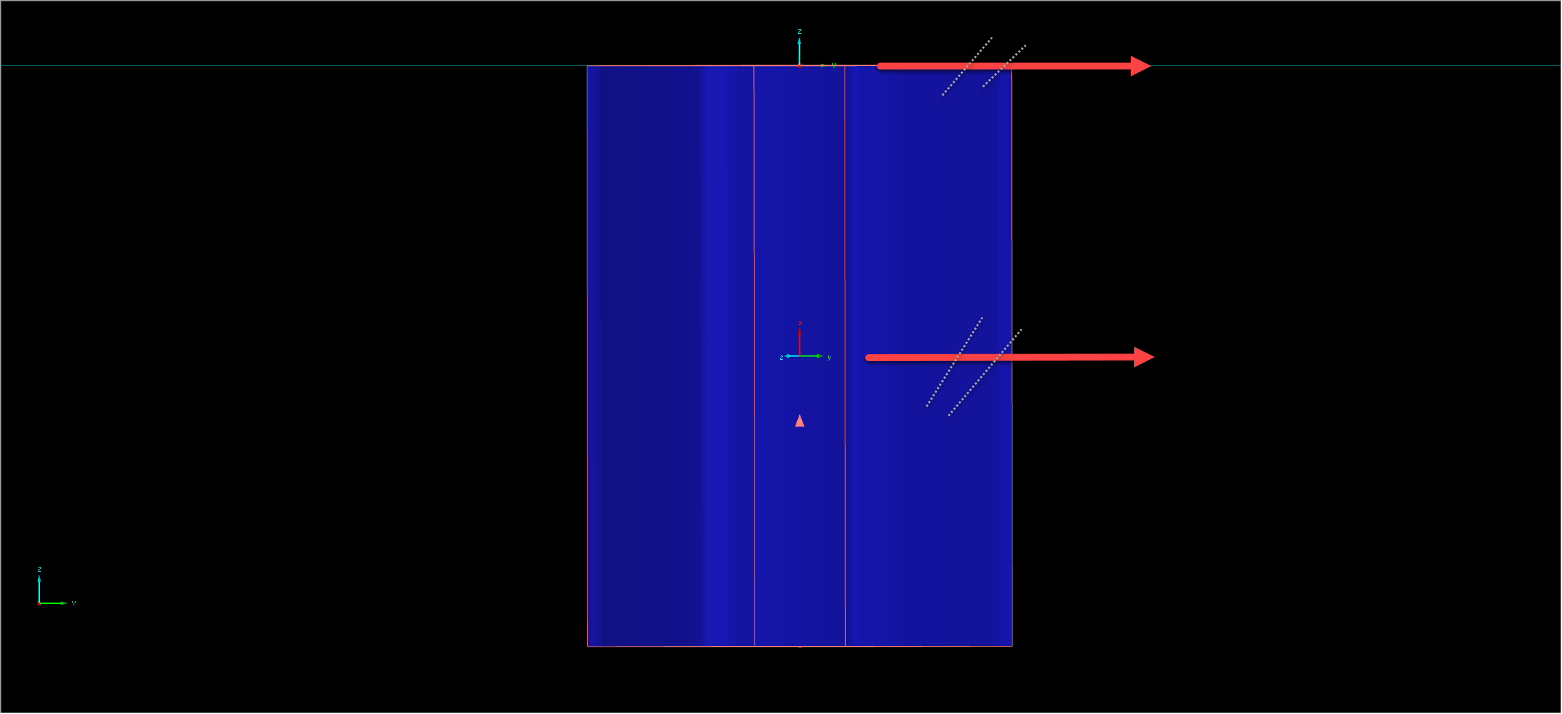
Example from a testing model: a member with node delta ΔX = −0.495 mm, ΔY = −0.320 mm, ΔZ = +302.71 mm (0.112° off vertical). RSTAB displays it with the orientation of a member lying in the global XZ plane (y ∥ +Y, z ≈ −X) - i.e. RSTAB appears to ignore the sub-millimetre ΔY but respects ΔX. This suggests RSTAB classifies member orientation against the global axis Z and the coordinate planes using an internal tolerance.
What we currently use: an angular tolerance of ≈ 0.081° (we treat a direction component as zero when 1 − cos θ ≤ 1e-6). This behaves correctly in the example above, but it is inferred from a single case and may misbehave elsewhere.
What we would like to know:
- What exact rule and tolerance does RSTAB 8 use to classify a member as vertical (parallel to global Z) or as lying in a global coordinate plane, for determining the default local axes?
- Is the tolerance angular (independent of member length) or absolute (a coordinate/length tolerance in mm)?
- Is the classification hierarchical (vertical first, then in-plane, then general), and how are ambiguous cases resolved (e.g. a member nearly parallel to both the XZ and YZ planes)?
This would let us reproduce RSTAB's member orientation exactly during import. Thank you very much for your help.
Kind regards,
Robin Blazek
IDEA StatiCa
Hi Robin,
-
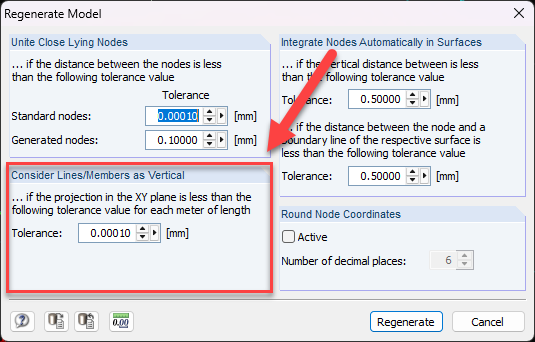
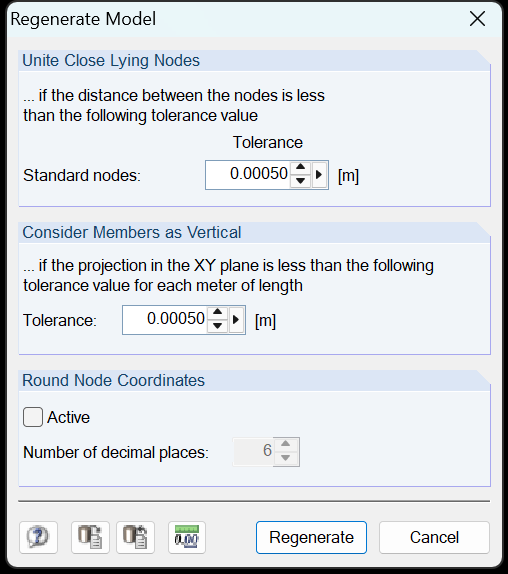
Whether a member is considered vertical depends on its projection onto the global X-Y plane. You can adjust the corresponding tolerance here:
https://www.dlubal.com/en/downloads-and-information/documents/online-manuals/rfem-5/004264
-
The tolerance is independent of the member length, as it is defined as the offset per meter of the member length.
-
There is no hierarchical classification. Only the following two states from our knowledge base article(https://www.dlubal.com/en/support-and-learning/support/knowledge-base/001449) are possible:
- State 1: The member is not vertical according to the criterion in point 1 → Case 1 (general position) applies.
- State 2: The member is vertical → Case 2 (vertical position) applies.
If you have any further questions, feel free to get back to us.
Best regards
Matthias
Hi Matthias,
thank you very much for your explanation.
If I understand correctly what you have described, the model I'm testing is then behaving quite unexpectedly.
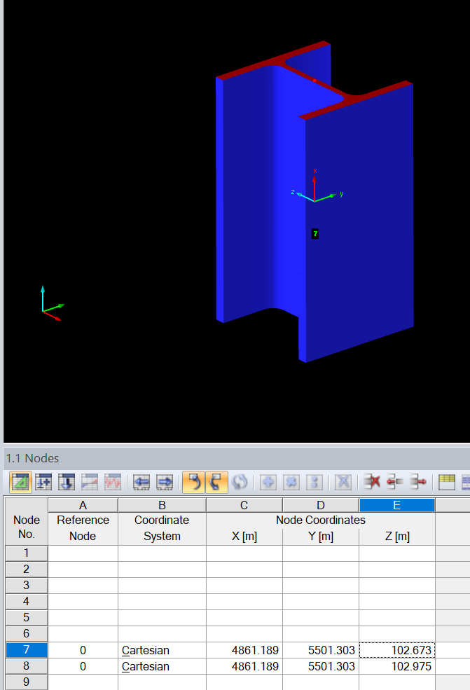
The coordinates I can see in the RSTAB UI are the same in global X and Y direction, so it actually looks like it is column - even in member table, it is marked as it's in XZ plane.

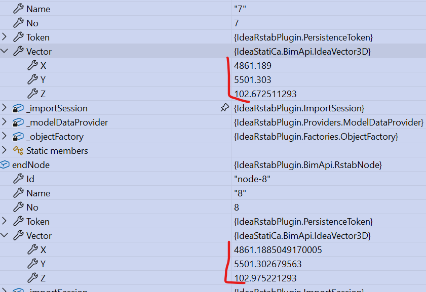
But in the API there are those tiny deltas I have mentioned before (ΔX = −0.495 mm, ΔY = −0.320 mm).
If I would apply the logic you have described - it definitely fails the check for tolerance of its its projection onto the global X-Y plane.
Which means that LCS should be created as for member. And it seems it kind of is, but not exactly. Because if you would calculate the LCS for member with those deltas, then it is basically rotated for about 33° from the base perpendicular global directions (those deltas are basically creating the direction rotated like by 213° or something). But in the UI, the LCS seems to be ignoring those deltas, and seems like LCS is "snapped" into the main directions. So that's why I thought there is maybe some more tolerance check applied or something.
To be honest, based on the quite weird coordinates, it seems to me like it was created either by API or by some import (we got it from the customer). So maybe it is somehow corrupted, I do not know. I have attached the model. Could you please just have a look at it?
LCS-test.rs8 (740 KB)
Thanks a lot for your time, I appreciate it!
Kind regards,
Robin Blazek
IDEA StatiCa
Hi Robin,
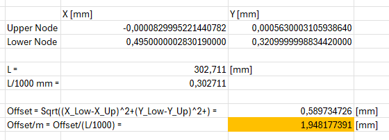
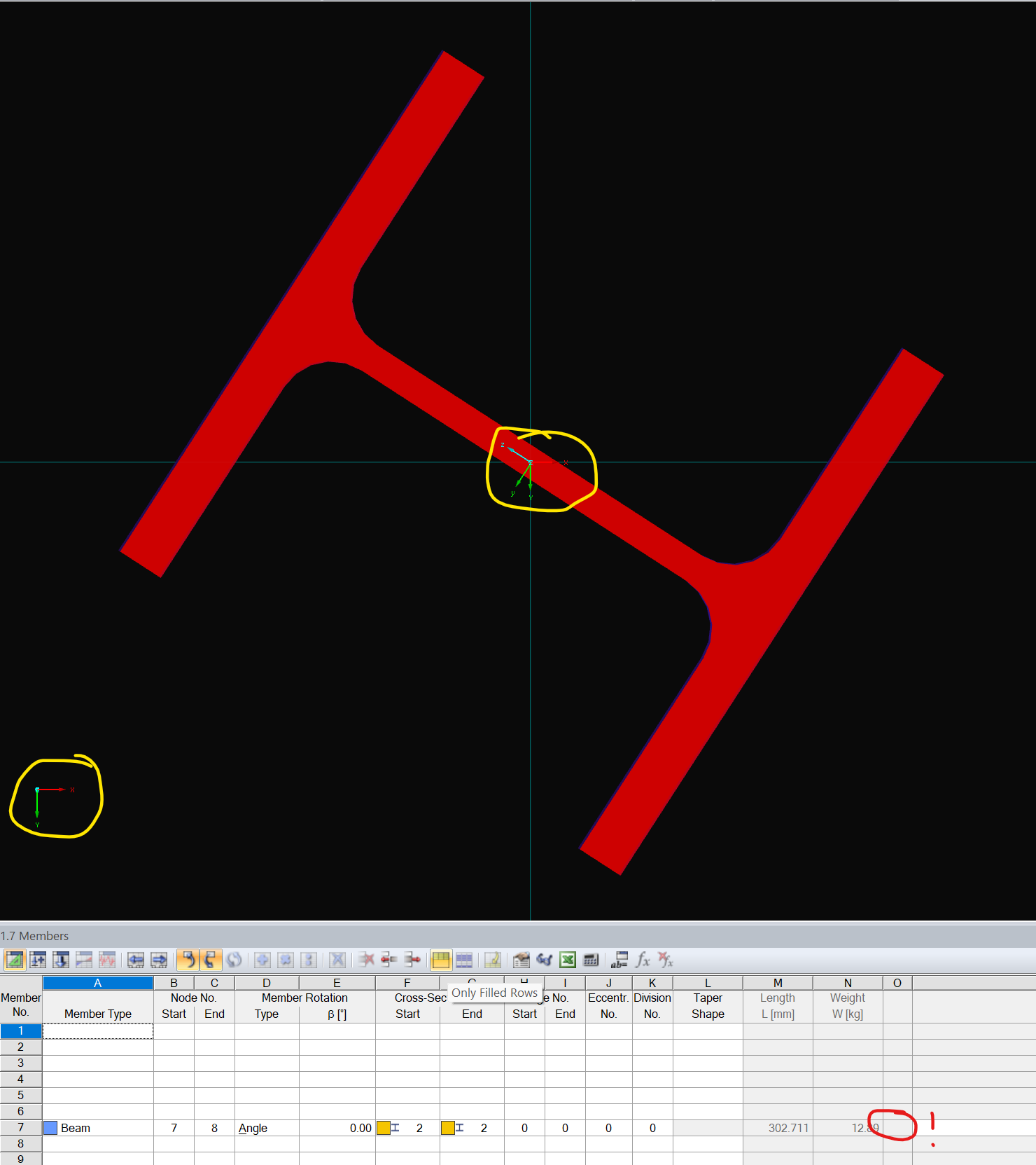
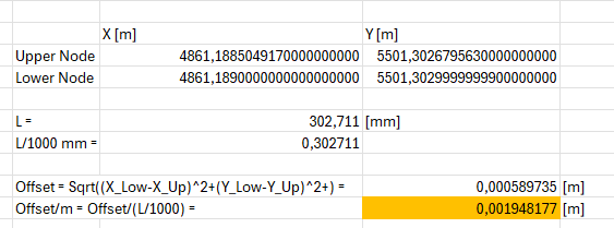
In your file, RStab behaves exactly as intended. The projection onto the X-Y plane is about 1.95 mm per meter of member length. This is definitely more than your tolerance of 0.5 mm. Hence, your member is not considered vertical. Hence, the local y-axis is parallel to the global X-Y-axis (Case 1). One possible issue with case 1 in the article is that the local z-axis must point in the direction of the global Z-axis. This may be wrong.
I translational moved the upper node of the member to the origin of the gloabl coordinate system and then calculated the offset in an Excel sheet.
LCS-test_moved to origin.rs8 (740 KB)
Best regards
Matthias
Hi Robin,
I have thought about it, and the section in case 1 regarding the direction of the local z-axis should be understood as meaning that the z-axis always points downward. This makes it clear which direction the y-axis must point in, since in case 1 there are actually always two possible directions for the y-axis, both of which are parallel to the X-Y plane.
Best regards
Matthias
Hi Matthias,
first of all sorry for a bit delayed reaction - I had couple of days off.
Thanks a lot for your responses. I went through them and I believe I understand your process of LCS creation correctly. I have checked the modified model you have sent and the moved member in your model fits the rules perfectly - I totally agree with that. I have actually tried to replicate the same thing on my original model - I have moved it into the origin and then it really is displayed correctly.
But the original model I have sent you still seems to me to be incorrect. I think that in a moment you move the member, it somehow "fixes" itself.
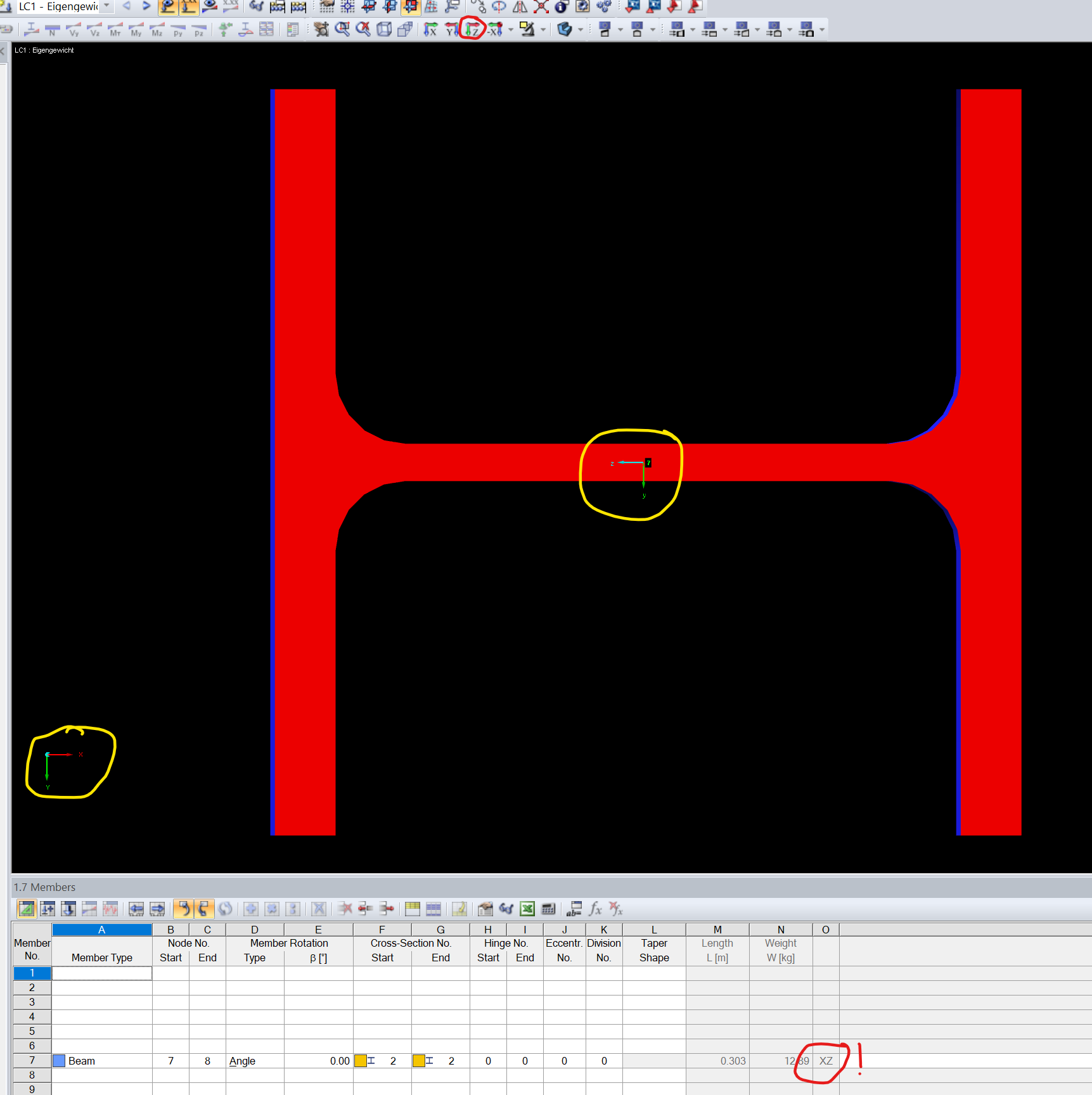
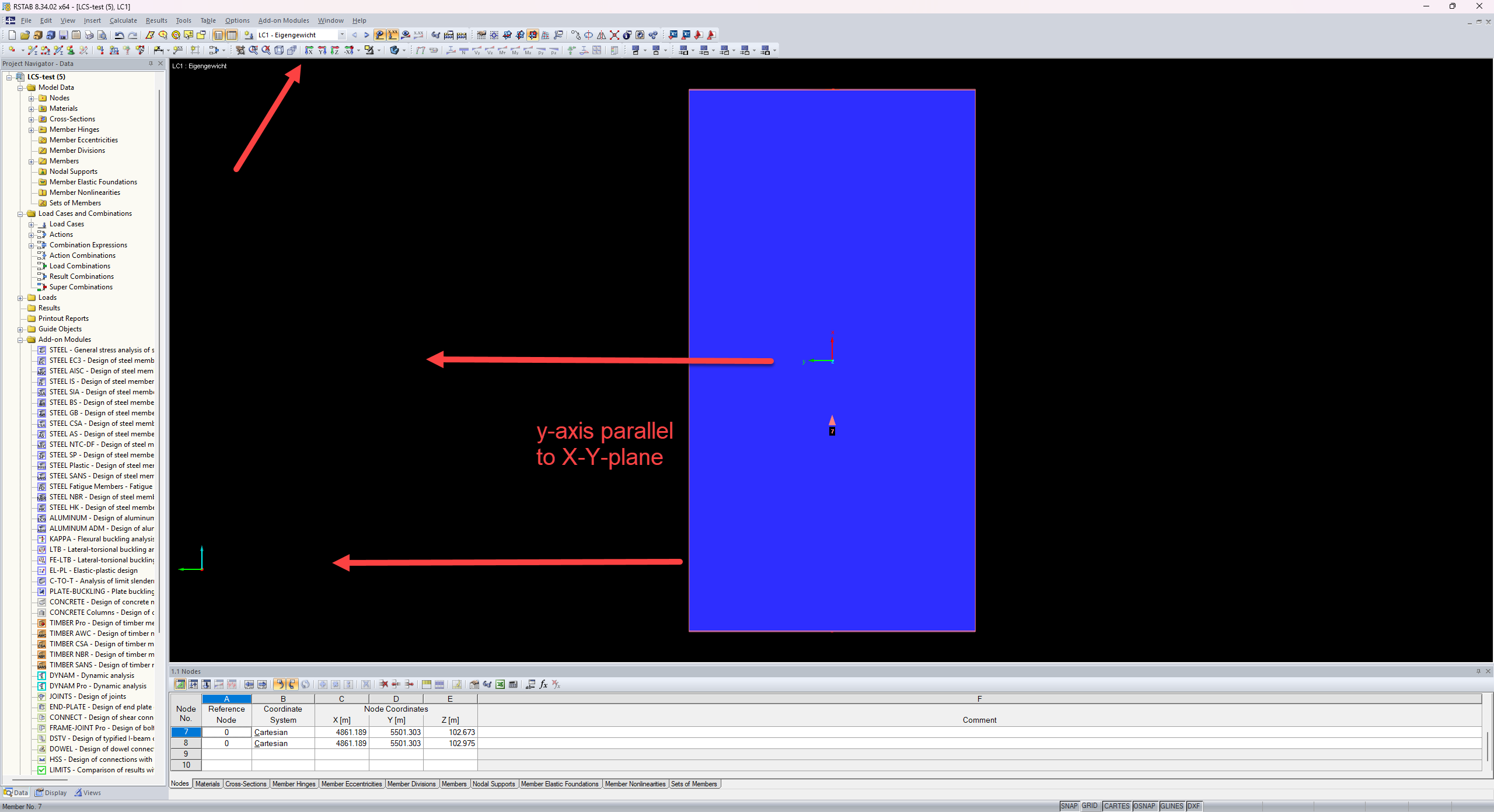
If you open model I have sent you and just display view in the Z-direction, it displays this:
So I read it as in the left corner I can see the GCS and in the middle of the member I can see LCS. And it looks like the global X is parallel to the local Z direction. Which is not correct.
I have noticed that in the member table it shows that the member is in XZ plane, which seems incorrect and suspicious to me.
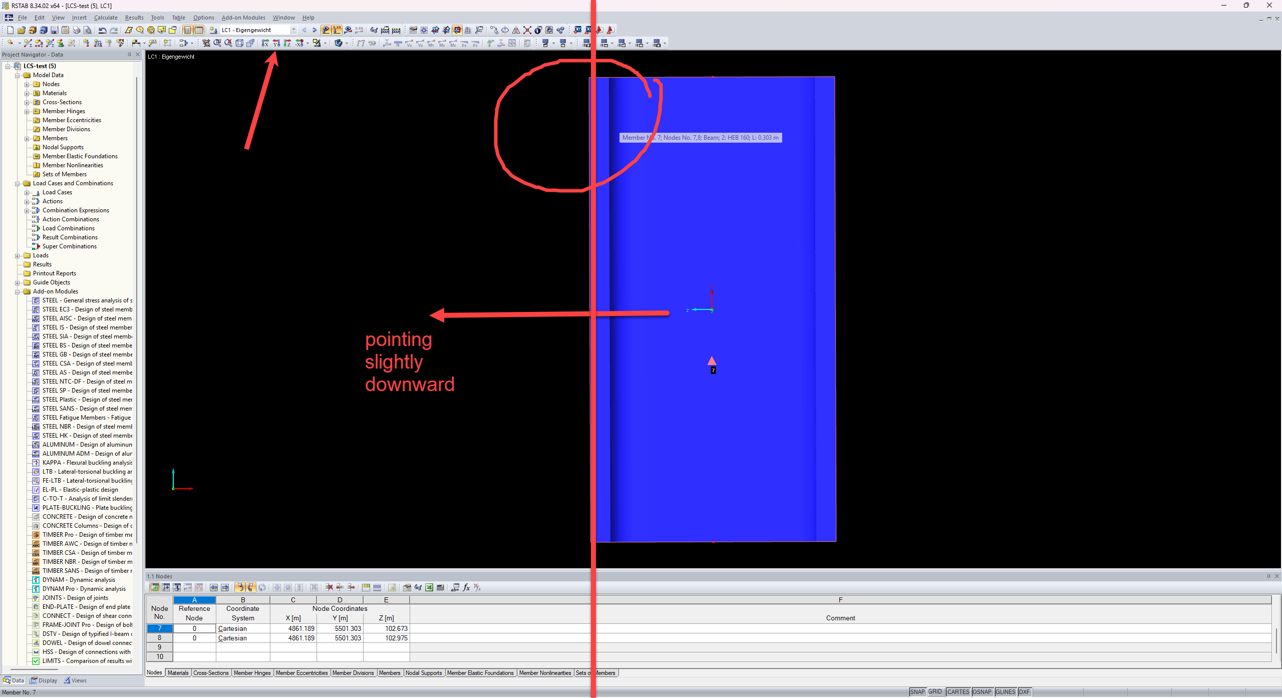
When I open model you have sent (or just move the member in my model to the origin) via translation vector you have mentioned and check the view in Z-direction you can see this:
That's completely different and I agree that this is correct. Angle between global X and local Z direction is there about 213° (or 33°, depends how you measure it). Also in the member table, it is no longer categorized as in XZ plane.
So can I assume from this, that the original model I have sent is really somehow corrupted? Maybe the problem is the huge distance from the origin point or maybe those very tiny deltas in X and Y directions.
Thank you very much!
Kind regards,
Robin
Hi Robin,
in your model, the local coordinate system behaves as intended. Since the offset exceeds 0.5 mm, the member is not considered vertical, and therefore Case 1 applies.
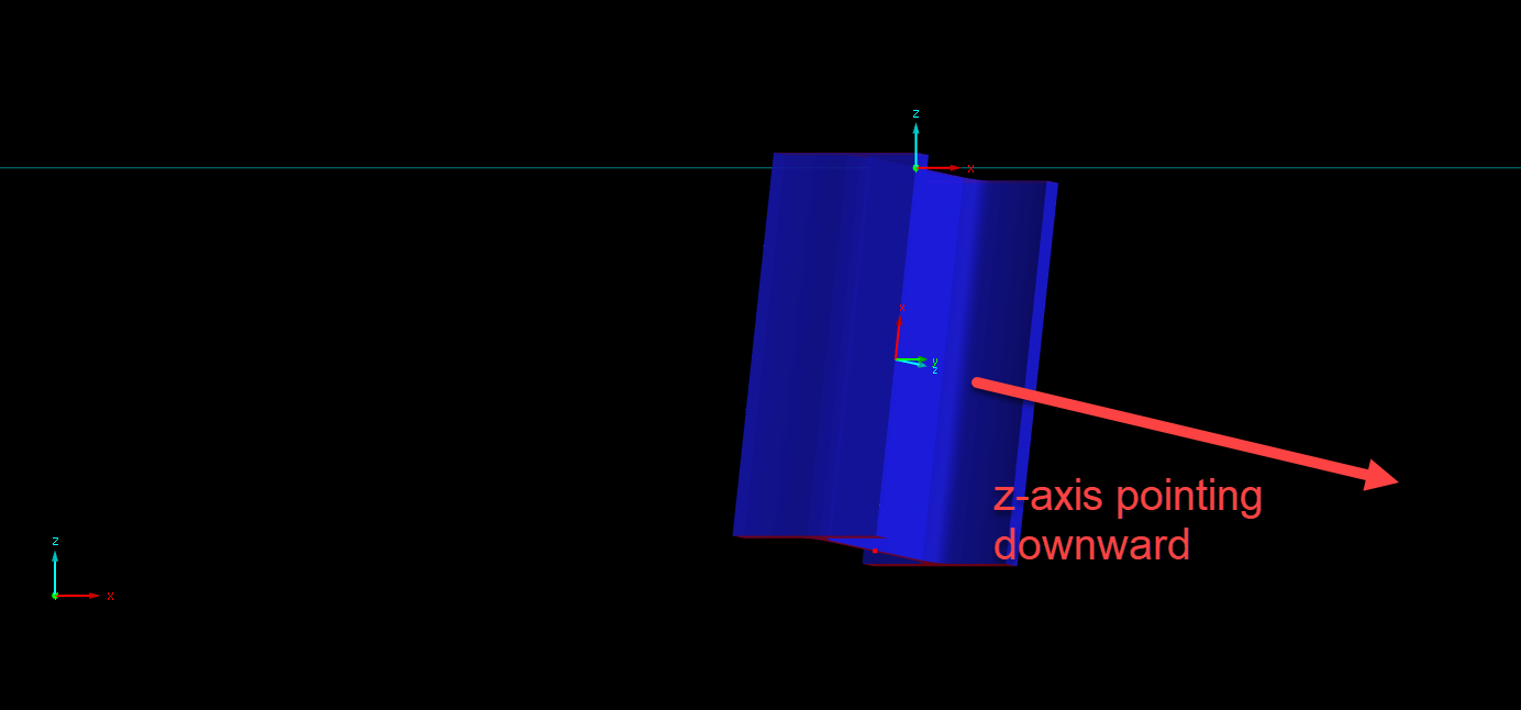
I only moved your member to the origin to make the downward-pointing local z-axis easier to visualize. This does not affect how the member is classified. Since the member is not considered vertical, the coordinate system is adjusted such that the y-axis is parallel to the X-Y plane and the z-axis points downward.
The further greater the distance to the origin, the harder it is to see to downward direction of your z-axis. It only looks like the global X is parallel to the local z-direction. But it is not.
Best regards,
Matthias
Hi Matthias,
I agree with everything you wrote in the last reply:
- member fails the verticality check, so Case 1 applies
-- agree
- local y-axis of the member is parallel to the plane X-Y
-- agree
- local z-axis points slightly downwards
-- agree
But the issue I pointed out in my previous message is basically the rotation of the member around its own local X-axis. That's why I have posted those images with basically looking perpendicular onto global X-Y plane. Because there you can see, that rotation of the member around local X-axis is looking completely different before and after you move it into the origin point. Can you explain this behavior?
Like I absolutely understand "the inclination" of local X-axis from global Z-axis. That fits the rules. But this rotation of LCS around its local X-axis doesn't make sense to me for the original position of the member. On the other hand in the case where you moved it into origin, it looks correct then.
I'm sorry that this conversation is getting quite long, I'm just trying to figure it out.
Thanks a lot for cooperation!
Kind regards,
Robin
Hi Robin,
Yes, you are right. Sorry about that.
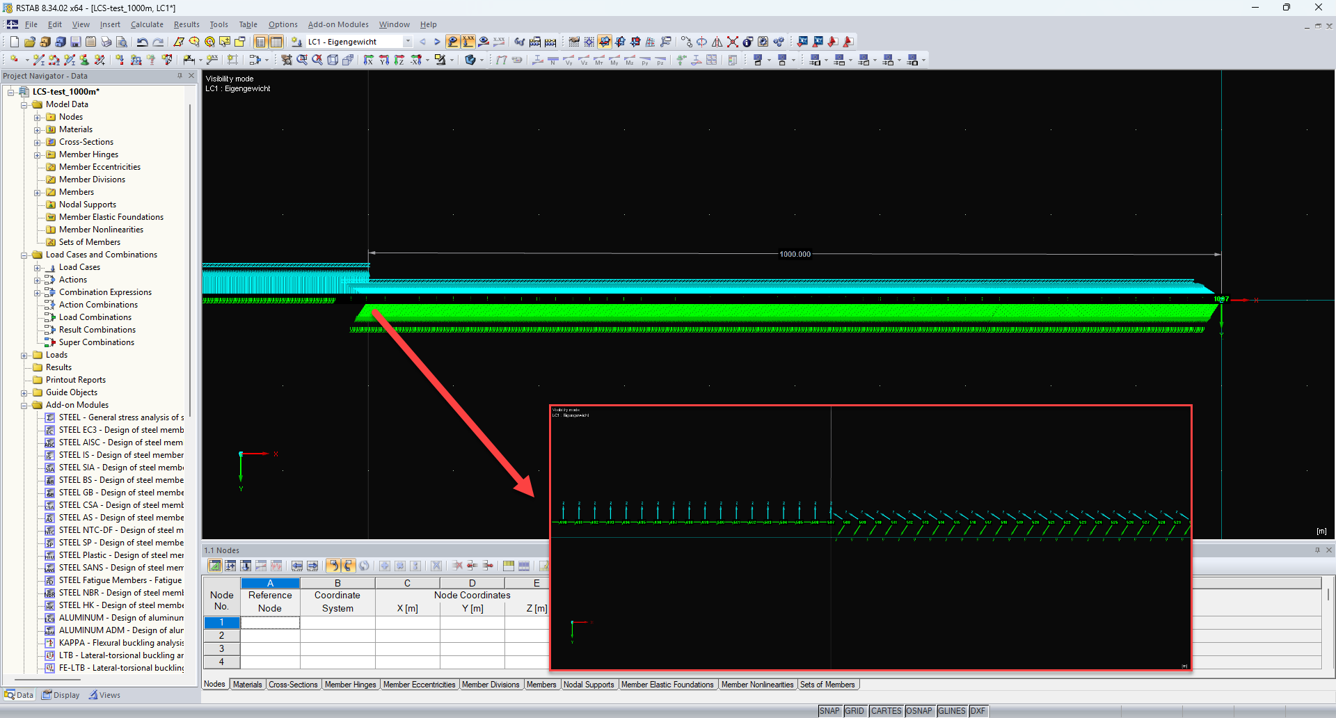
The behaviour suddenly changes at a distance of 1000 m from the origin. So, it seems that for distances greater than 1000 m, the local coordinate system is oriented as shown in case 2:
Unfortunately, I could not find out whether this can be adjusted. In RSTAB 9 / RFEM 6, the behaviour is consistent over the entire distance.
Best regards,
Matthias
Hi Matthias,
great, thanks for confirmation! We will consider it as some kind of edge case with unexpected behavior and for creating the LCS, we will use the rules which you have provided before.
I consider this topic as solved.
Thanks a lot for cooperation, I appreciate it!
Robin