Good day,
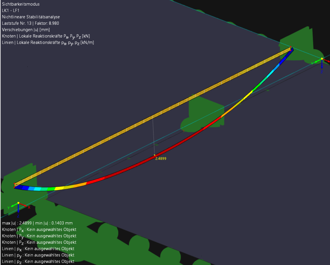
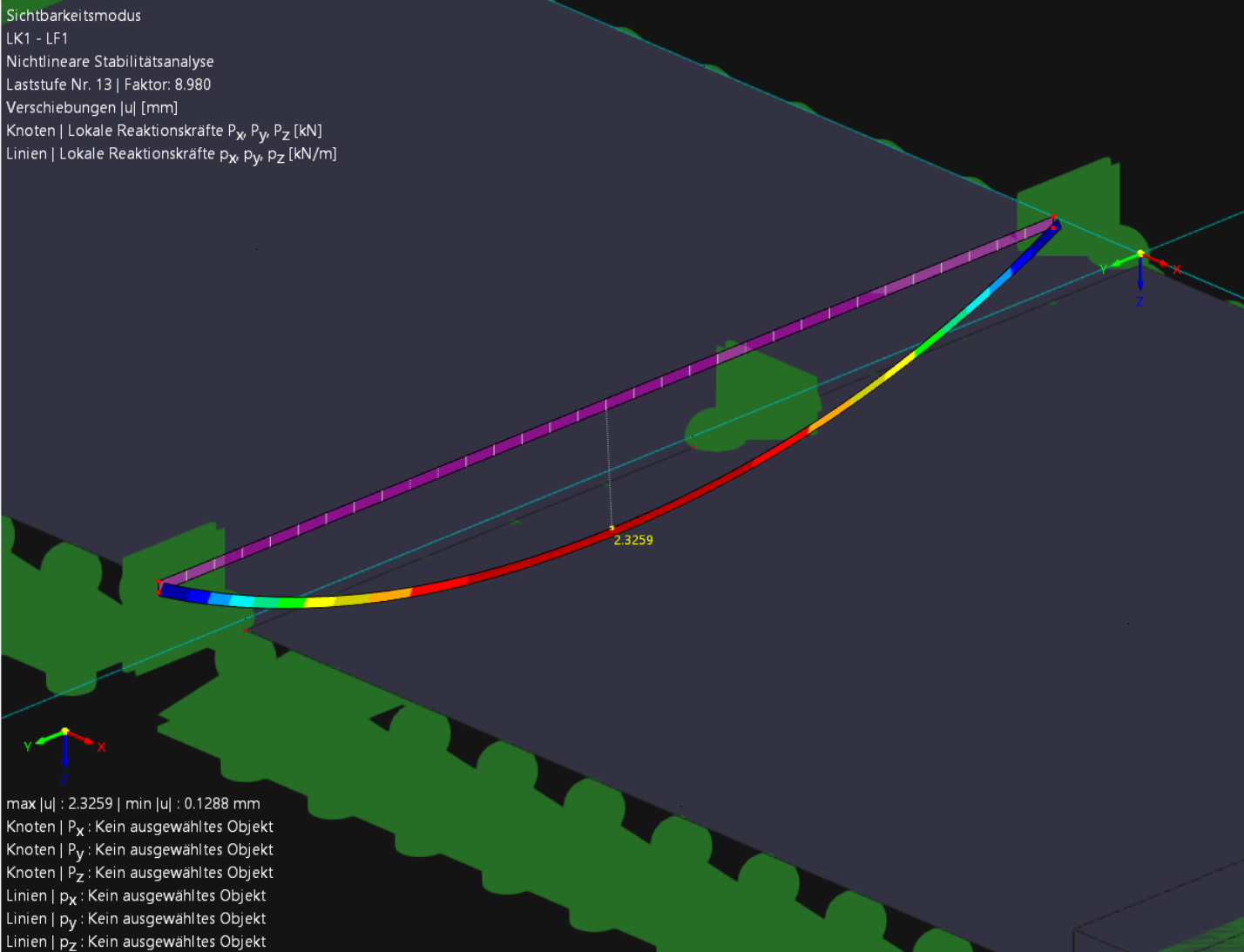
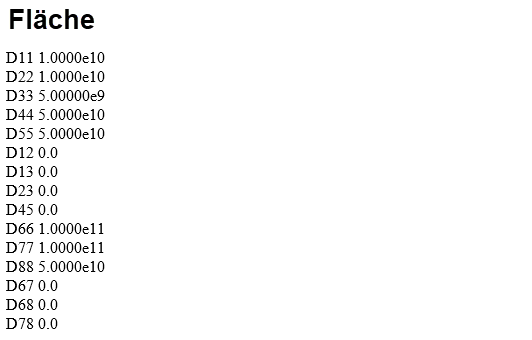
I am currently using RFEM6 to conduct an investigation on eccentrically impacted buckling panels. An earlier modeling approach for the eccentric impact of the two sheets was to connect them via a rigid surface. I have discarded this approach again because I believe that the transverse stiffness in the impact area is significantly overestimated this way. However, I was surprised when I looked at the deformation results of the rigid surface in the limit case of GMNIA. These appeared very high to me. Since the rectangular rigid surface has nodes at all corners that have contact with a line held in the Z direction, I would expect that the deformations of the rigid surface result at most from a translation in the X direction (loading direction). I suspect that the rigid surface must also have a finite stiffness/thickness, as infinity cannot be quantified, but the deformations that occur are, in my perception, far too high. I am sending two models (without results) named "Starr" and "Dicke40mm". In the model named "Starr," the eccentricity is modeled as a rigid surface, and in the model named "Dicke40mm," as a surface with a thickness of t = 40 mm. The resulting deformations of the coupling surfaces are very close to each other.
Additionally, I am sending two images showing the results of the maximum deformation |u| of both models in the limit case of GMNIA. I would be very grateful if you could help me understand the circumstances that lead to this deformation behavior of the "rigid surface."
Dicke40mm.rf6 (1.3 MB)
Starr.rf6 (1.3 MB)