Good day,
As part of my master's thesis, I am dealing with eccentric sheet metal joints near transverse stiffeners and the effects of eccentricity on the load-bearing behavior.
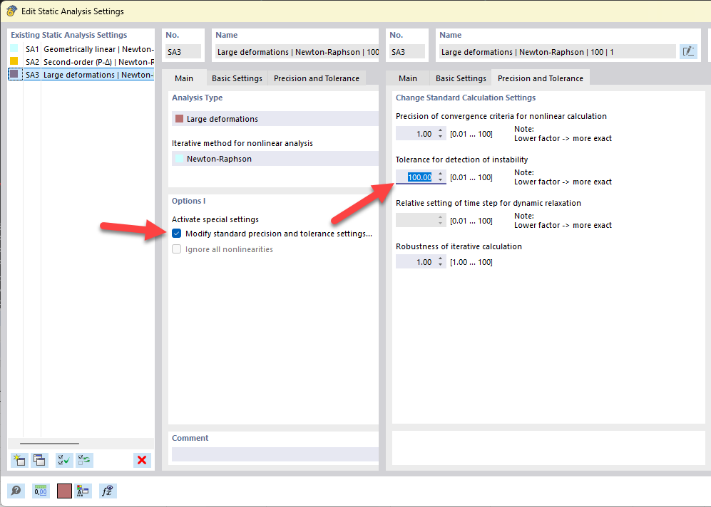
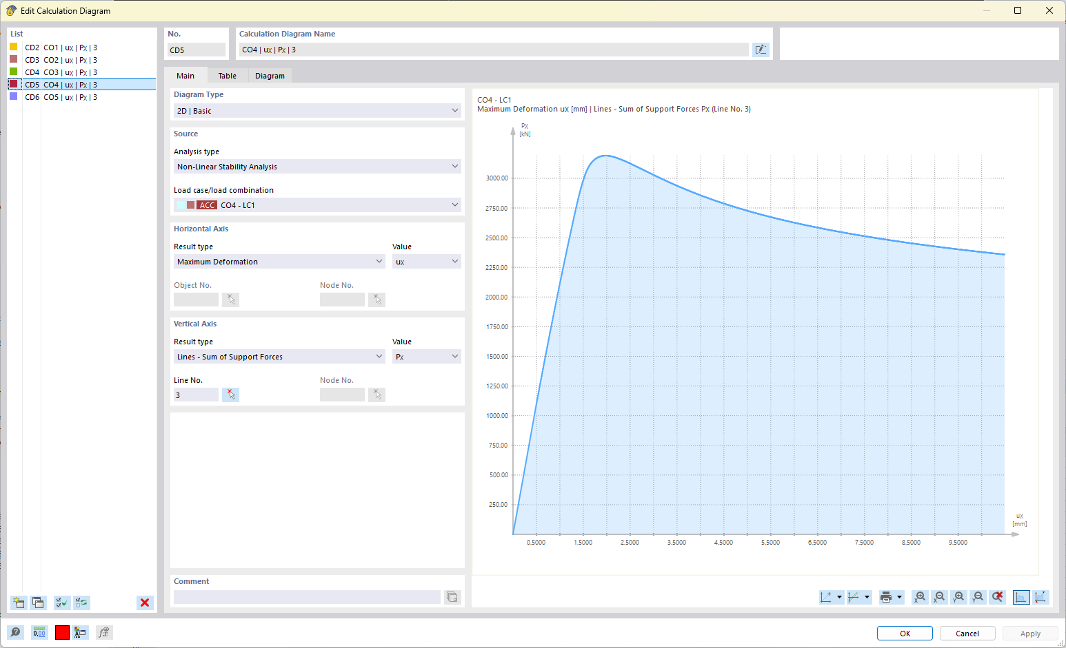
For this purpose, I would like to conduct a parameter study and would like to perform the calculations of my models using arc-length control. To approach the matter, I have modeled a very simple rectangular plate (1 m x 1 m; t = 12 mm). I want to initially limit myself to uniaxial compressive loading. I have supported the sheet metal all around with a Navier support in the Z direction. As an initial load, I applied a line displacement of 0.1 mm in the X direction on one line. This line and the opposite line are additionally restrained in this direction. Through a linear buckling analysis (LBA), I determined the first five eigenmodes and derived imperfections from these with an amplitude of b/200. These imperfections are considered in the nonlinear stability analysis with a nonlinear material model (GMNIA). The further calculation settings can be found in the attached model.
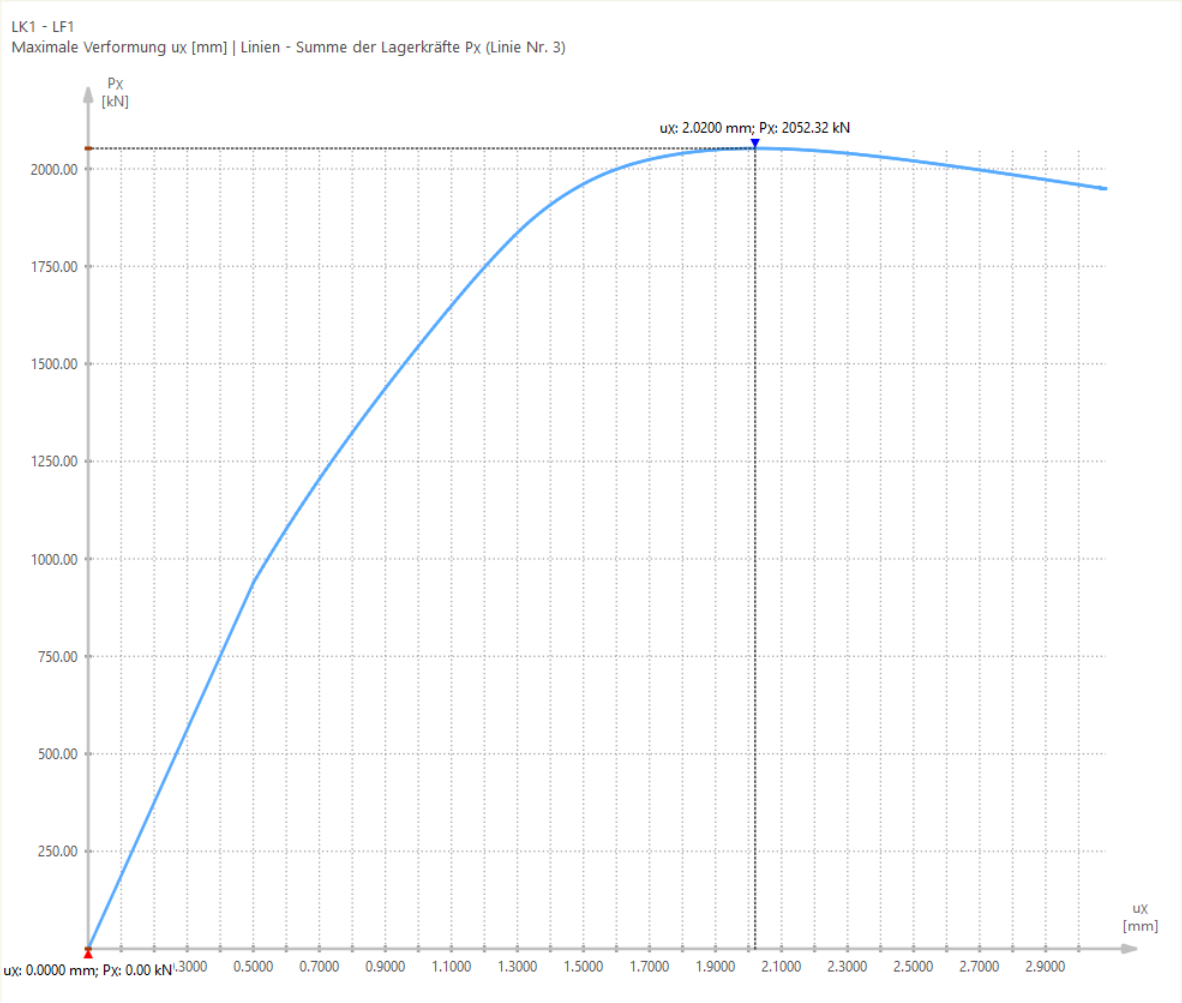
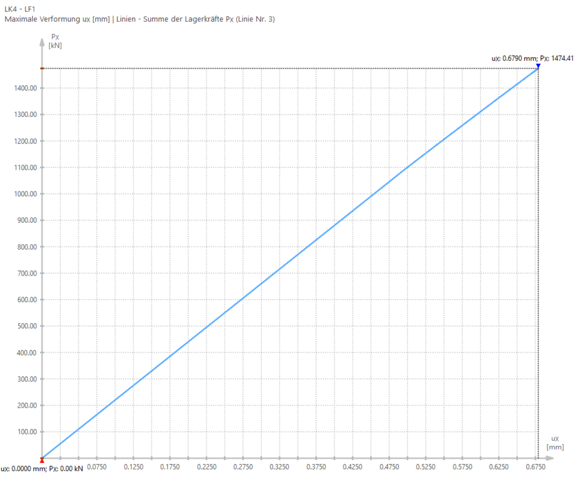
The calculation results of the first two load cases (imperfection from eigenmode 1) look good. The load-displacement diagram can be plotted beyond the limit load (see Image 1). The calculation of load cases 4 and 5, according to the load-displacement diagram, breaks off far too early (see Image 2). The results of the von Mises equivalent stress also show that the material in these load cases does not even yield at the last achieved load step.
RectangularPlate_ArcLength.rf6 (1.1 MB)
My questions are therefore:
- Why does the calculation stop before reaching the limit load?
- Is there a calculation setting I can adjust to reliably increase the load beyond the limit load as in load case 1?
I would be very grateful for help with my problem :)!
Thank you very much in advance!
Best regards
Philipp Schultheis