Full of anticipation, I went to the office today expecting to measure, label, and attach the node I identified yesterday from the steel connection addon according to my protocol. The plan was to use the 3D-DXF export.
Attempt 1 was to do everything using REVIT (currently my strongest CAD/BIM program). At first, it wasn’t at all obvious how to import a 3D-DXF, but eventually it worked → Problem 1: Revit turns the entire import package into a family of the type “Imported Symbol.” You cannot select individual lines or components (not even by tabbing through multiple selections). Edges, etc., are recognized for dimensioning, but only for that purpose; otherwise, it is not possible to explode or break apart the imported geometry. Problem 2: In Revit, the entire connection consists only of lines; since there are no surfaces, lines and edges that should be hidden or invisible are visible in sections and views.
After longer unsuccessful attempts to somehow explode or resolve the whole thing, I initially gave up on Revit.
Attempt 2: Measuring and labeling the connection in RFEM in the connection dialog. Initially, I was still excited in the first few minutes because everything is displayed very nicely and colorfully, but:
Problem 1: Unfortunately, there is no option to create sections or multiple views, which theoretically works perfectly outside the connection dialog and simply needs to be implemented here: views, layers, section planes.
Problem 2: You cannot hide individual labels/comments, so I would either have to label every single component, rib, plate, etc., in one view, which becomes incredibly confusing and no longer evaluable, especially for more complex connections, or after labeling a view, I would have to screenshot it, delete the annotations → switch to the new perspective and label again. But if I want to edit the first view again, I have to start all over.
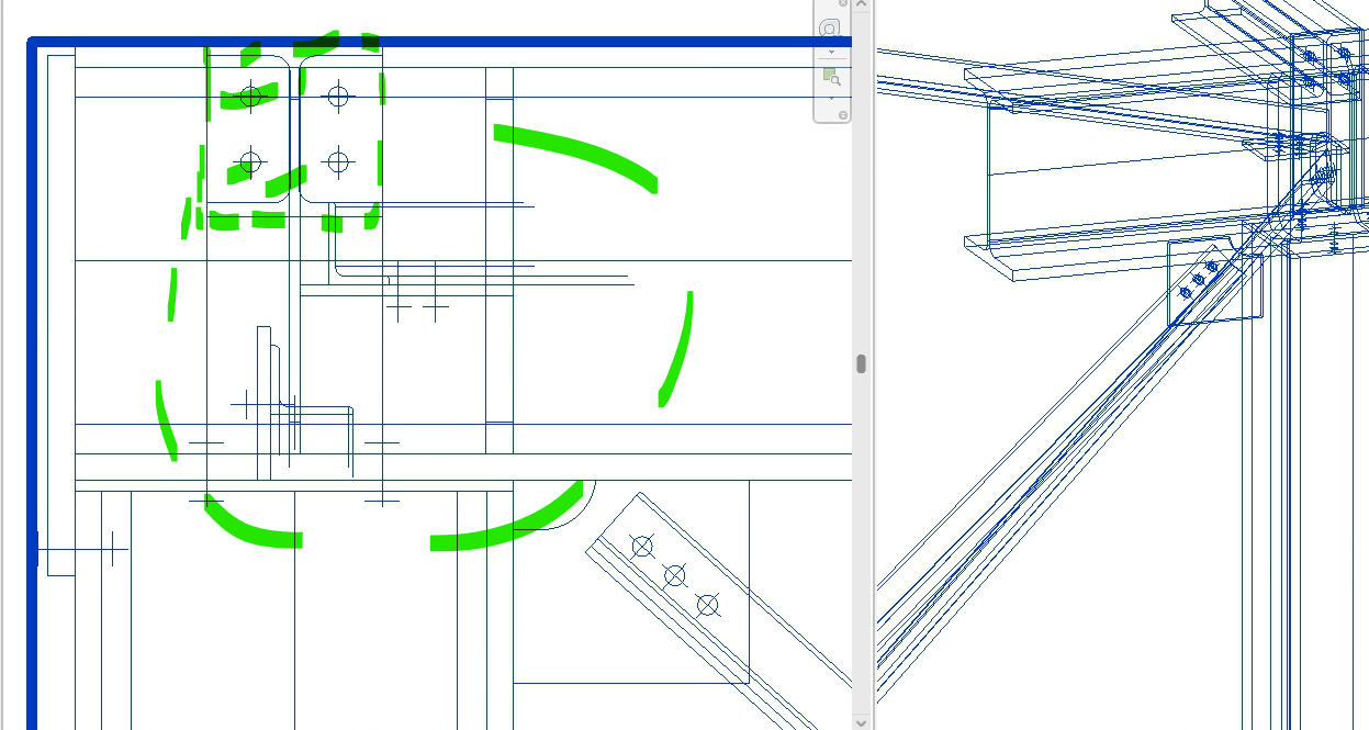
Attempt 3: AutoCAD (which is probably the intended software). Unfortunately, it is the CAD software I am least skilled in. The plus side here is that the file can be imported very easily and all lines can be selected and edited, etc.
The difficulty here again is that the entire connection consists of single lines and is thus “transparent,” so initially hidden lines are visible in the views again, etc. Since I must admit to being relatively clumsy with “regular” AutoCAD, it would be interesting to read how others proceed here to document connections from RFEM6 as quickly and efficiently as possible, which functions, etc., do you use after import? Is there any video material / workaround guide, etc.?
I look forward to any input and am happy to share my progress if it goes better :)