Hello,
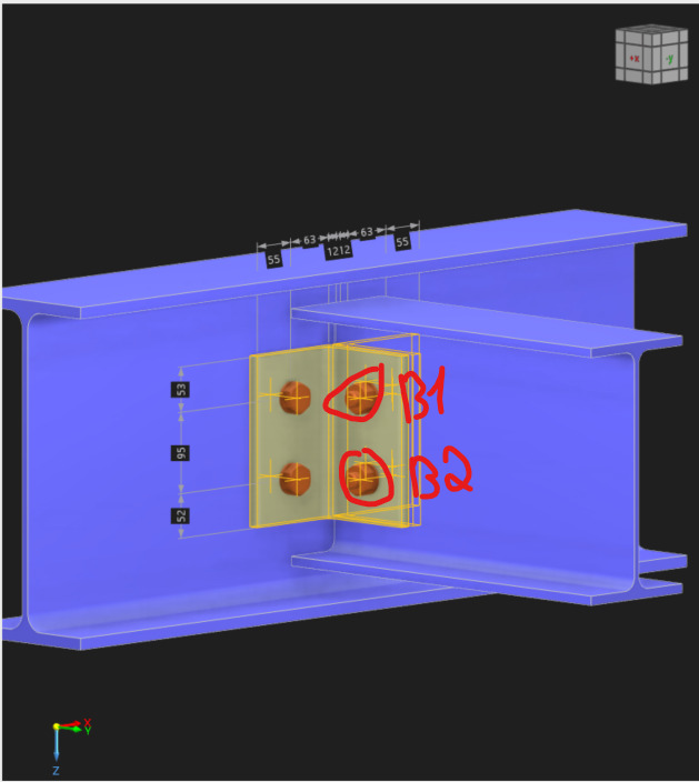
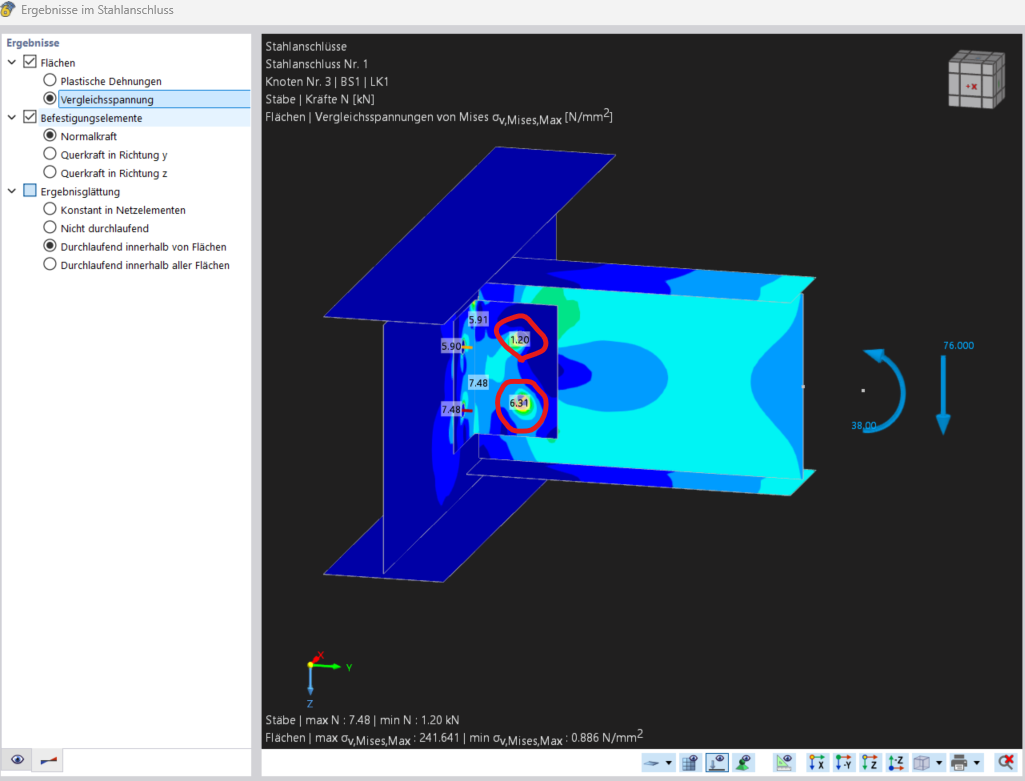
I created an articulated angle connection in RFEM 6 with non-prestressed bolts (M20-4.6) and calculated it using the Steel Connections add-on. Regardless of the support conditions of the system, RFEM 6 Steel Connections calculates a tensile force F_t,Ed in bolts B1=1.20kN and B2=6.31kN on the secondary beam (Image 1). For B1 and B2, it is not immediately clear to me why the bolts should experience tension. In a manual calculation (or with Frilo), the tensile forces for B1 and B2 are always zero. I also have no load in the X- or Y-direction that could generate a tensile force F_t,Ed.
Attached you will find the RFEM file.
winkel2-ohneErgebnisse.rf6 (2.7 MB)
Hi Eric1998,
first of all, welcome to the community.
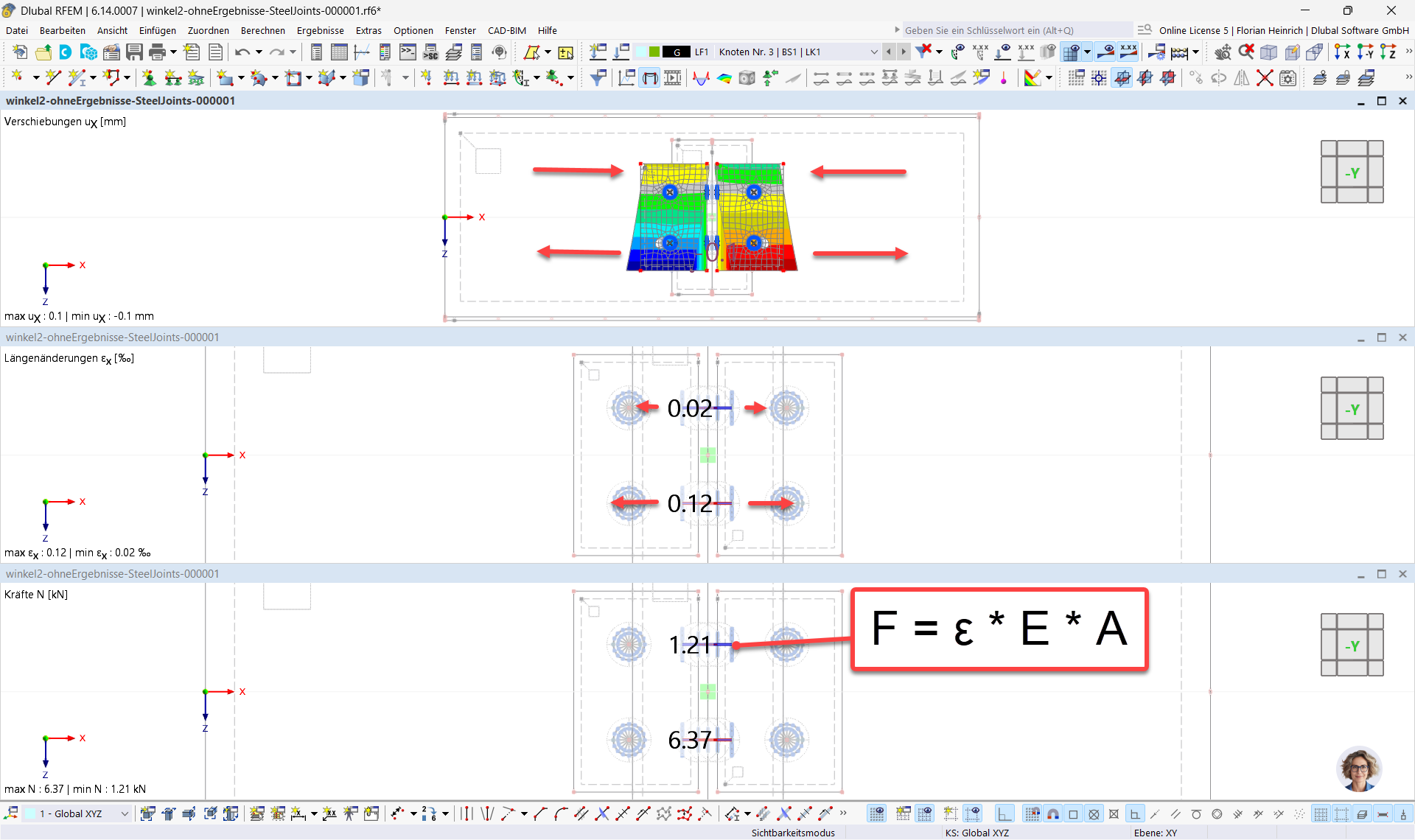
The tensile forces in screws B1 and B2 result from the mutual twisting of the angle profiles (see illustration above). This twisting leads to a longitudinal elongation of the screws (see illustration in the middle).
Since the displacement of the angle profile in the X direction increases with decreasing height, screw B1 experiences less elongation than screw B2. Since the normal force is directly calculated from this longitudinal elongation, the upper screw B1 consequently has a smaller tensile force than the lower screw B2 (see illustration below).
These findings come from the FE model of the substitute steel connection ("submodel"). Further details and theoretical background can be found in the online manual:
How you can open and analyze this submodel directly in the program is explained step by step in this video:
Best regards Florian Heinrich
Hello Florian,
Thank you very much for your feedback. Your response was very helpful.
Best regards
Eric Thiry