Hello.
I am currently modeling a maintenance platform that is supported on composite beams made of 2 U-profiles. RFEM shows me a deformation of over 1 m. That can't be right, as the platform is already partially erected and the actual deflection is indeed greater than in the original static calculation, but certainly not to this extent. So far, I haven't even fully applied the load assumptions in the model.
- Can someone give me tips on whether the composite beams were chosen correctly?
I want to stiffen or connect the two U-profiles with plates. However, the Steel Connection add-on is not working for me – I can't get it to run and don't know why. Additionally, I am having trouble inserting the last ribs in the front U-profile.
Thank you very much for your help!
Best regards
Maik
Wartungsbühne.rf6 (2.4 MB)
Hello Maik0501 and welcome to the Dlubal Community👋,
thank you very much for your exciting question!
In the load-bearing capacity of composite cross-sections, the shear connection plays a decisive role. In your model, you have represented the composite U-profile without shear connection. This means: The two U-beams can slide independently of each other and thus only carry load individually.
However, as soon as the two beams are connected to each other – for example by connection plates or screws – so that an effective shear transfer exists, the load-bearing capacity increases significantly. 
If you want to consider a shear connection, proceed as follows:
-
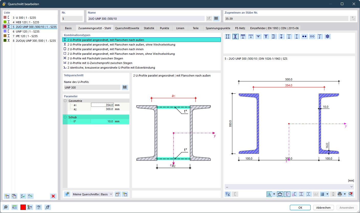
In the model, select the green-marked combination type shown in the following image, i.e., with interaction.
-
Then define the shear thickness.
Note: For discrete connection points as in your example, determining the value is not trivial – here it might be worthwhile to consult technical literature.
 An important point: The modeled steel connections cannot be recognized as shear connection by the composite member, since here member analysis meets an FE submodel.
As an example: With a shear thickness of 10 mm (analogous to the upper image), the torsional moment of inertia of the cross-section increases from 68.06 cm⁴ to 26,165.85 cm⁴. The influence of the shear transfer is therefore enormous.
In practice, this means for your model:
- The previously non-converging LP1, which showed deformations in the meter range in the non-converged state, now leads to a maximum deformation of about 30 mm with the adjusted cross-section.

The steel connections look fine to me at first glance. They calculate without problems with the adjusted cross-section.
Could you please describe more precisely what information or results you still need for the steel connections? That way we can help you more specifically.
Thank you very much, the results already look more realistic. 
- However, I now have the question of how exactly the shear thickness t* works.
Graphically, it looks like two continuous horizontal plates of 10 mm between the U-profiles.
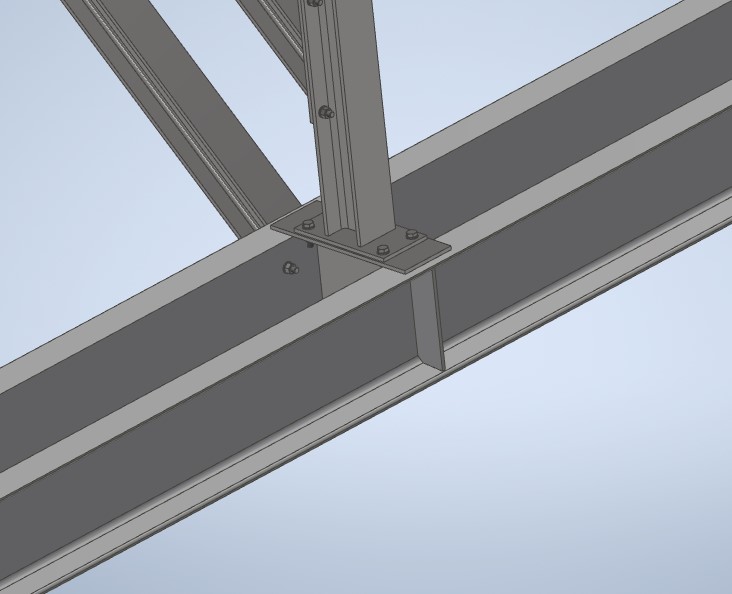
In my model, however, there are only four "vertical" 10 mm plates. As shown in the following picture.
- Can I continue to work with the given shear thickness that RFEM suggests to me?
Otherwise, I would have built a model similar to the following.
Wartungsbühne -1.rf6 (2.0 MB)
Because what is important at the moment is not the connection, but to what extent the U-profiles twist or deform.
(I was able to fully model the steel connections in the last model thanks to the tip with the shear thickness. Thank you very much)
Glad to hear you made progress with the steel connections.
The determination of the shear thickness t* is exactly the crucial point in your case. 
The 10 mm I mentioned earlier was just a fictitious value for illustration. The actual shear thickness will be significantly smaller with the given sheet metal arrangement.
To determine a realistic value, you could proceed as follows:
- Verify the shear thickness on your most recently sent alternative model.
- Make sure that the deformations between both models are approximately the same size.
- Once this is the case, you have found a plausible value for
t*.
Overall, I think your alternative model is a very good idea. It is excellent as a reference and comparison.