RFEM6 Pilecap Error 1327

Hi,

I am currently working through how to use the geotechnical analysis. I previously got it working for a simple concrete surface founded on a soil massif generated by a borehole. I am now trying to design a concrete pile cap.

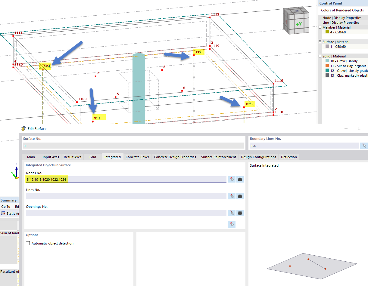
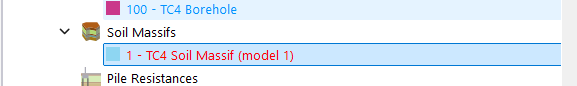
I have modelled it as follows:

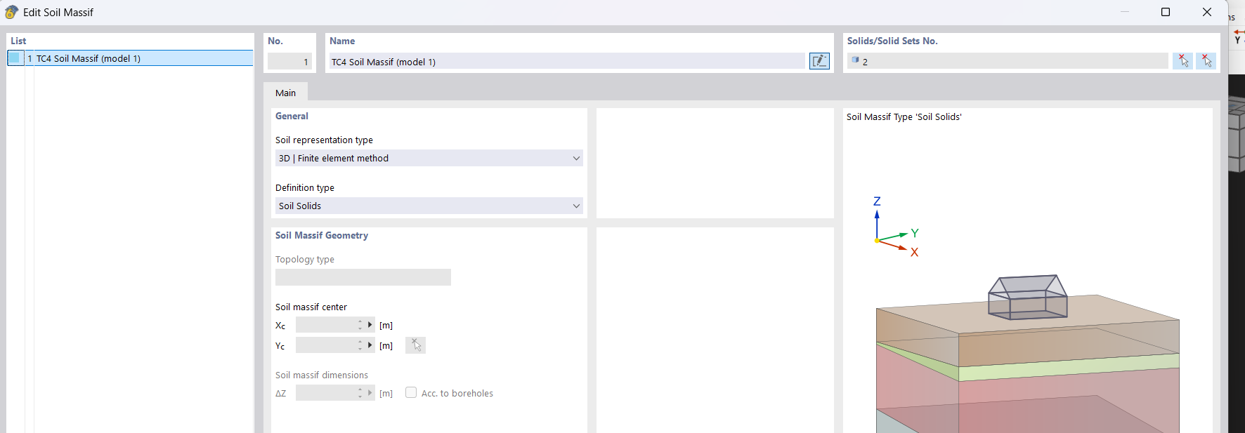
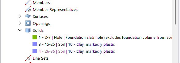
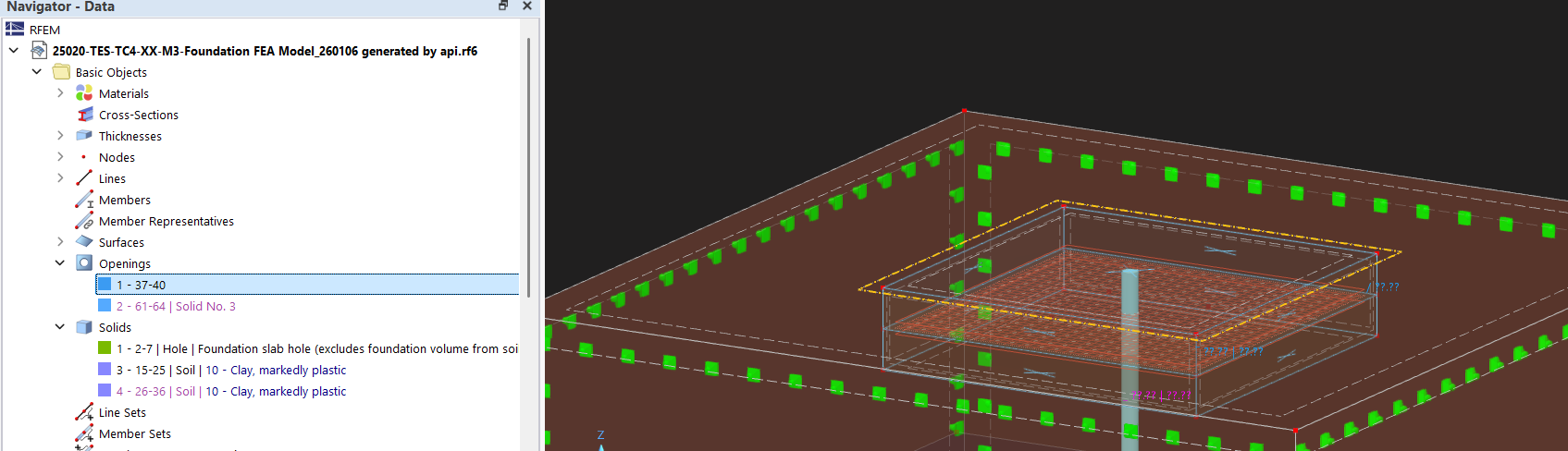
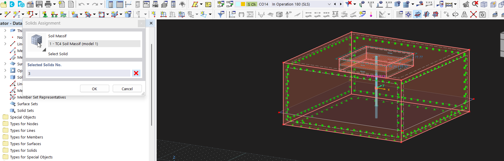
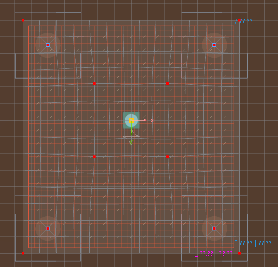
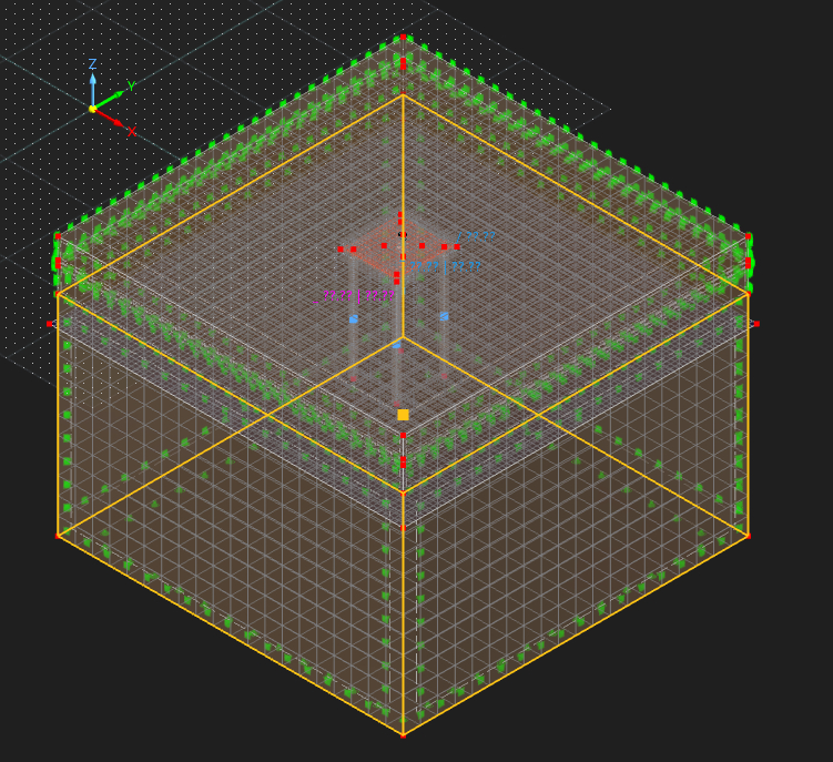
I have created my reinforced concrete surface. I have modelled piles as members (without design for now as a first step). When I generate mesh and look at top view the nodes of the piles are integrated in the mesh, so it is connected. I have added an eccentricity of half my slab thickness to the pile so that it starts at the bottom (I have tried running without and I get the same error). Note that I just have 1 pile member which goes through multiple soil solids (I don’t think I need so split them?), but do have varying pile resistance. I have set the pile lines as integrated objects in the solid (interestingly when I use the lines I used to create the pile and then run the calculation it says to remove them, and then requires me to integrate lines which are auto generated and show up as line releases). I am designing it as a suspended slab so I have not integrated the pilecap to the top solid as I don’t want it to bear on the foundation.

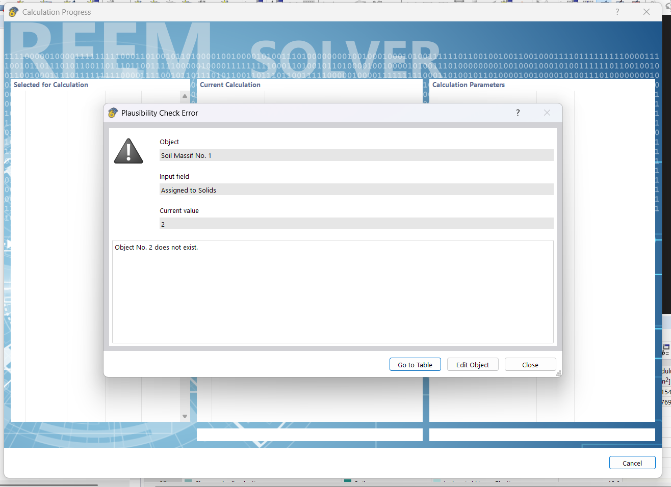
When I run the calculation for a load case I get Error 1327 Calculation Failed.

I found this online and it says to update to the latest version (which I have done) and check there is space on C: drive (which there is).

Error 1327: Calculation Failed

Is it likely a modelling problem that I have done wrong? As I mentioned I’ve never modelled a pilecap with member piles so I could be doing something wrong. Its not very descriptive with what to troubleshoot. I ran the model checks and the plausibility check but couldn’t find anything wrong.

Thanks,

Samuel

Hi Samuel,

thanks for your message!

To analyse the problem more precisely, the model file would be very helpful:

:right_arrow: Click on FileSave as and choose the following settings to reduce the file size:

image

image467×393 7.53 KB

:right_arrow: Then upload the file here (e.g. *.rf6, *.rs9) – this way, the community can also contribute to the solution.

:owl: Prefer not to share the file publicly? No problem – send it to me via direct message: click on my profile picture or user nameMessage.

Best regards
Eike Hartmann

Hi Samuel,

thank you for your message. I’ve taken a look at your model and would like to share a few helpful hints and clarifications with you.


:pushpin: Excavation / Soil Modeling

At the moment, the slab is placed inside the soil volume and overlaps it. An excavation should instead be modeled using solid intersections / Boolean operations, as described in the following FAQ:
:backhand_index_pointing_right: https://www.dlubal.com/en/support-and-learning/support/faq/005523

A practical demonstration of how to work with solid intersections can also be found in this webinar. Please refer in particular to the chapter “Uneven terrain”:
:backhand_index_pointing_right: https://www.dlubal.com/en/support-and-learning/learning/webinars/002741


:pushpin: Pile Modelling

In the current program state, the released nodes at pile top need to be manually integrated into the slab by the user. If you activate display of node numbers you can see the IDs of released pile top nodes that should be added to the slab.

You are absolutely right regarding the pile modeling:

  • The pile should not be divided into parts

  • The correct approach is to model one pile as one member and apply varying pile resistance, as you did.


:pushpin: Pile results

Regarding the dialog during the calculation run asking you to integrate objects: this will be improved.

In the meantime, please note:

  • Line releases can be used to evaluate the shaft friction (see line release results)

  • Nodal releases allow you to check the pile tip force (see nodal release results in the result tables)


If you have any follow-up questions, just let me know — I’m happy to help.

Please see below an image regarding the pile top nodes that should be integrated into the concrete surface.

Hi Juliane,

Thank you so much for that detailed reply, it has cleared up a lot of confusion surrounding the correct modelling process!

My first question: I have two different scenarios, one where I integrate the surface into the soil as I want it bearing (ie a slab on ground), the other is a suspended pilecap which I don’t integrate (as I want the pile to take all the loads not through bearing). Do I model a solid over the volume of the surface and set as type hole for both? Or does integrating the surface do this automatically?

My second question:

I am using the python API to generate my model. My approach is to create the surface which has a 2m thickness, then I nodes, lines, surfaces and then a solid (of type hole) which is the volume of the surface (with its thickness). I then create the soil massif.

In the generated model, the soil massif is showing up as red (error), and when I run it has the below error.

image

Which is because the soil massif I created via boreholes (that RFEM6 automatically converts to a solid, which I mentioned in RFEM6 Soil Masiff Type) is assigned to solid 2, but in solids the api created 3 and 4?

I note that 3 is in back text indicating that it is generated by soil massif from solids, and 4 is in purple indicating that it is generated by soil massif from boreholes (I think that’s how it works). Both 3 and 4 soil solids are correct, ie they are the soil solids (generated by the soil massif) without the volume from the solid hole.

It also generates two openings.

I have tried to call the code that creates the soild hole in different locations, as described below, but all generate the same model with the same issues.

  1. Before the soil massif
  2. After the soil massif
  3. After the soil massif in a separate create objects call.

I have the same issue regardless of if the surface is integrated into the soil solid or not.

So to fix it manually, in the soil massif under solids, I reselect solid 3 in graphics. It runs, but then I have two solids and I am unsure how that affects the mode.

I also want to know how to generate it properly with the api to avoid this issue?

But then in the results there is no interaction between the surface and the soil solid. This makes me think that the answer to 1 is that we do not have the hole if we are integrating it? Or if we are meant to, there is another issue?

I have private messaged you a copy of the model generated by the API.

Sorry for bringing an API question into this but I figured it was best to keep it all in one thread.

Thanks in advance,

Samuel

Hey,

Just as an update if anyone refers to this post for guidance on the topic:
As a workaround to the API solid hole not working (or maybe my inability to code it), I have found it easier to just have the surface on top of the soil solid. IE the top surface of the soil solid is at the same Z as (the surface z - half thickness).

For that approach you need a surface contact between the two (which I didn’t realize before!).

Previously in one of my posts I think I mentioned I was integrating the surface to the soil solid, but I have realized this is wrong, and you should only integrate lines for a pile to the soil solid.

Also, personally when designing a pilecap I made the decision to separate it so that I have one model for the pilecap (modelled as a surface), with nodal supports (as fictitious columns), and then another model with one pile (and the governing loads) in the soil solid.

Thanks,

Samuel

1 Like