Hello,
I have modeled a moment-rigid flange plate connection in RFEM 6.
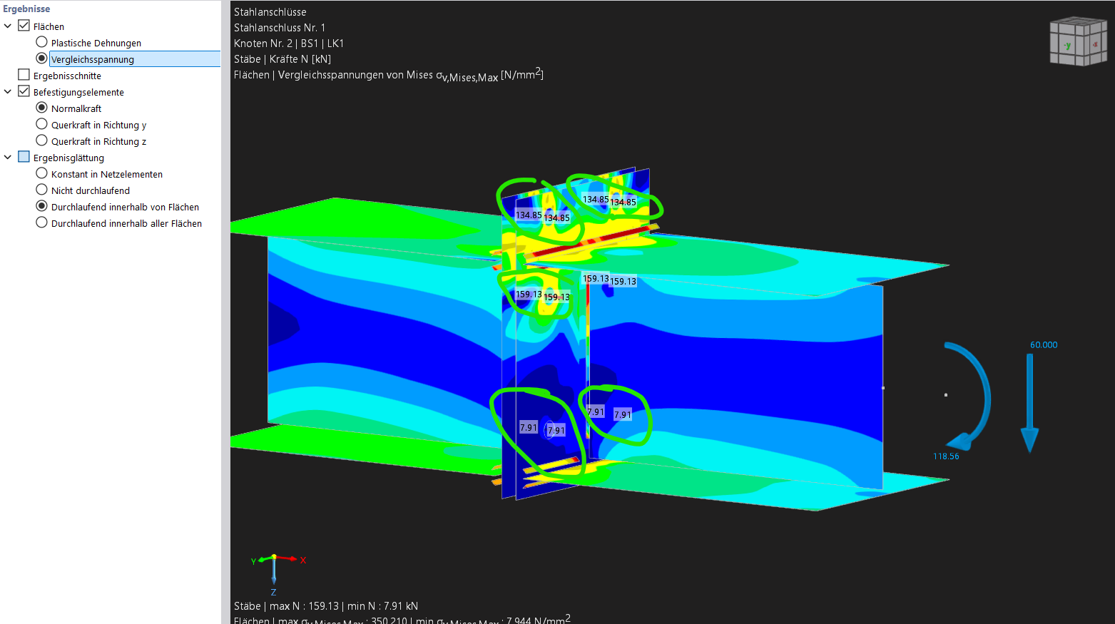
My question concerns the tensile forces in the bolts (marked in green in the attached image). In a rough hand calculation, I obtain higher tensile forces than RFEM 6.
For the upper bolts, RFEM 6 indicates a tensile force of Ft,Ed = 134.85 kN. For the hand calculation, I used the design moment My,Ed = 145 kNm and the lever arm between the compression flange and the upper bolt pair of h = 0.3035 m. This results in: Ft,Ed = 145 kNm / 0.3035 m = 477.8 kN. This corresponds to the resultant tensile force in the upper bolt pair. If this force is evenly distributed between the two bolts, the tensile force per bolt is about 238.9 kN. Could you please explain to me what causes this deviation?
Additionally, I have a question regarding the welds of the connection.
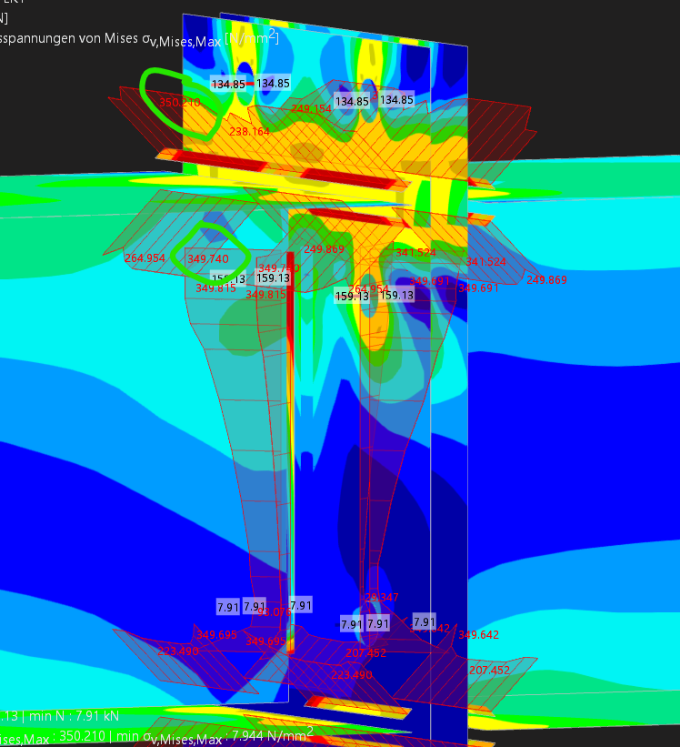
For the welds, the opposite picture emerges: while the tensile forces in the bolts from the RFEM 6 Steel Connections add-on are lower than in my hand calculation, higher stresses are indicated for the welds than the values I calculated (equivalent stress in the compression flange = 161.4 N/mm² and in the web = 114.9 N/mm²).
Could you explain how RFEM 6 Steel Connections add-on determines the weld stresses and which effects are taken into account?
Attached I am also sending the RFEM file.
Stirnplattenanschlussttest1.rf6 (1.4 MB)
Best regards
Eric Thiry